
I’ve had several projects going on more or less simultaneously over the last 6 weeks in connection with the build-out of the 1st module of the L&NC. One project has been to further refine block occupancy detection in DCC to achieve 1 mA detection sensitivity—the sensitivity needed to detect rolling stock equipped with a 10kΩ resistor wheel set. High sensitivity occupancy detection will be especially useful in the Red Bluffs yard part of the layout I’m working on right now
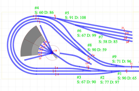
This part of the L&NC is a Yard/Staging facility with a roundhouse & turntable, so it has lots of blocks
Commercial block occupancy detection systems for DCC typically use current transformers to sense current draw from locomotives or resistor wheelsets. The sensors are usually attached to stand-alone logic boards that turn outputs on or off to signal occupancy detection. Typically, these outputs are used to directly power signals. The December 2016 issue of Model Railroader Magazine included an article (Build a signal system with Arduino micro-controllers) where the author connected the outputs of RRCir-Kits BOD boards to an Arduino Mega, and ran his signals from there.
I’ve been avoiding solutions like that because of the high cost and inflexibility of commercial detection systems. All I need is a way to sense very low current flow; the Arduino can do all the rest of the work.Thinking about the issue further, I wondered why not just use current transformers as sensors that can be directly read by an Arduino?
Finding Experimental Sensors
Current Transformer
The type of current transformer useful in model railroading are designed to allow you to wrap a wire (e.g. track feeders) around it through the central hole making the wire the “primary” coil of the transformer. The secondary coil produces an A/C current, that you can measure, proportional to the A/C current running through the primary wire.
I had seen little about using CT sensors with Arduino until I bumped into a seller on Amazon of boards with current transformers marketing them as Gikfun DIY 5A Range AC Current Transformer Module for Arduino. The assembled boards were about $7.50 each, a bit expensive, but then I found a 5 sensor unassembled kit from the same vendor for just under $9. Less than $2 per sensor is my price point for BOD sensors, so I bought the kit to see what i could do with it.
Gikfun Current Transformer Kit
The kit consisted five current transformers, five 82Ω resistors, connector pins and five 19mm x 19mm pc boards on a break-apart strip, drilled and traced for the parts. The resistor is placed across the transformer leads, placing a load (I’ve seen it referred to as a “burden”) on the transformer enabling current flow. No instructions on how to use the sensor were anywhere to be found.
So I went with the methods I already know work with ACS712 sensors. I set up some feeders from the DCC system to my cleaning track, wrapping one of the feeders around the CT coil three times. I hooked leads from the sensor board to pin 0 and ground of my Mayhhew Labs Extended ADC Shield, then threw together a test sketch with the current reading utilities I’d previously used (adapted for the shield).

A Simple CT Sensor Test Rig
I “let her rip” and watched the readings go by on the serial monitor.
Oh My! Putting a DCC equipped locomotive on the track and turning track power on, I was rewarded with a clear reading even though the decoder was idling and all lights were off. Bring up the lights and the readings jumped up appropriately. Then, taking the loco off the track, I tried shorting the track with a 10kΩ resistor: an immediate and clear response in the readings told me this was going to work.

Test readings in single ended mode using a Mayhew Labs 14 bit ADC Shield. Everything from a 10k resistor shorting the track, to different stages of locomotive operation are clearly shown by the sensor outputs.
I tried it again, this time connecting the CT sensor to A0 and ground on my UNO, and got different but workable results. Amazing!

The readings through the UNO’s built-in ADC are similar, especially at the low end. But notice that the scaling, which is spot-on correct in the first example, fails at higher current levels here. Evidently, the greater bit depth of the Mayhew Labs Shield (14 bits) vs the built-in ADC’s (10 bits) makes a difference where absolute accuracy is concerned. Our purposes are much cruder — we just want to know when a minimum current (1 mA) is flowing. For that purpose direct-to-UNO works fine.

Testing current sensing with and InterMountain EMD F3A
Wait! This Shouldn’t Work!
You see, I was using the ADC in “single-ended”, “uni-polar” mode so that it would read a single input in the range of 0 to +5 volts; this is the same way Arduino analog inputs are read by the built-in ADC. However, the signal from the CT is an A/C signal that the ADC (in single-ended, uni-polar mode) will not be able to read during the negative voltage part of the cycle. Nevertheless, it works with both the built-in and the external ADC, even though it shouldn’t.
I was puzzling as to why, apparently, I was able to cheat when it occurred to me that the difference from ordinary applications was probably the frequency of the signal. Ordinary A/C is a 60 Hz cycle (60 cycles per second). That is slow compared to the rate at which an Arduino ADC can sample, so a lot of samples would be at 0 during negative phase of the cycle. This would throw calculations off.
DCC is an 8kHz (8000 cycles per second) cycle which is very fast. My Mayhew Labs ADC can sample at a maximum rate of 3kHz, which is somewhat faster than the Arduino built-in ADC but still slower than the DCC cycle. So even at the fastest rate every ADC read will span multiple DCC cycles, resulting in the ADC returning a positive reading every time.
Or something along those lines is going on.

Mayhew Labs Extended ADC Shield on an UNO, reading the test CT sensor in differential mode.
For hard core accuracy, a CT should be read in differential, bi-polar (+/- voltage) mode, requiring a 14 or 16 bit external ADC with that capability. In differential mode, each CT lead is attached to an ADC port, then the two ports are compared and their difference reported. This effectively captures the entire A/C cycle. Read in differential mode, CT sensors produce stable, high accuracy readings. During testing with my 14 bit ADC I was able to sense down to near 400µA in differential mode, the draw of a 20kΩ resistor at 11 volts. Now that is sensitive!

Same test sequence using the Mayhew ADC to read the sensor in differential mode. Notice the increased accuracy, stability and sensitivity.
Next Steps
The Gikfun 5 sensor kit is a viable sensor package where you will be watching no more than a few (up to the 6 or 8 analog ports on your Arduino or Mayhew Labs ADC shield) blocks. For small installations, buy these sensors and use the ADC in your favorite Arduino board to read them.
For larger installations, the external ADC shield is worth the cost because it is fast and more accurate.
But what if you are watching more blocks than you have analog ports for? That is a bit of a problem, especially if you don’t want to have to use a new microcontroller for every 8 blocks. The module I’m working with has this problem, because it is a yard zone (with turntable and roundhouse) with 24 blocks, and I want just one Arduino board to listen to them all and run signals for this part of the layout.
In the next post, I’ll go into a solution to the problem and install the system.
Code
My experiment was complicated by the fact that I was testing different ADC’s and different connection methods. Below is some basic code for testing a CT sensor such as the Gikfun units discussed above by directly attaching one lead to an Arduino analog port, and the other lead to ground. This is the simplest way to use CT sensors.
The code is built around current sensing techniques originally developed for ACS712 sensors. For more in-depth discussion of that development process, see these posts – 1 , 2, 3 and 4. ADC’s (analog-to-digital converters) read the voltage produced by a sensor which, in the case both current transformers and ACS712 sensors, is proportional to the current it is measuring.
The challenge with sensing alternating current comes from the fact that at any given moment when a sensor is read, the current could be anywhere in its cycle with a voltage somewhere between -Vmax and +Vmax (the nominal A/C voltage). Since we are sampling a bipolar wave form, it is necessary to take multiple samples spanning multiple cycles, then calculate the current from the samples using the Root Mean Square algorithm. This is the generally accepted method for determining A/C voltage and current from digital samples.
In addition to solving the basic problems of sampling an A/C signal, the RMS algorithm cuts through signal and sampling noise, a significant problem with ACS712 sensors when measuring low current. Since CT sensors are far less noisy, we can get accurate readings with fewer samples; but we still need the RMS method to calculate current flow.
To make the process I’ve described accurate across an array of sensors, I developed a calibration routine. All ADC’s will produce some minimal reading for a sensor even when the sensor is not producing a signal. This is a form of noise that has to be filtered out. Also, some sensors (such as the ACS712) produce a signal in the absence of any current to measure — this too is noise that has to be filtered.
Each ADC port / sensor combination will produce a unique amount of noise. The purpose of the calibration routine is to measure and record the noise level — I call it ADC Zero — for each port/sensor. This is recorded both as raw mV, and as a calculated current in mA. Later, the measured noise is subtracted from each raw reading (in mV) to determine what current (if any) has been detected. Then, when current is detected, I use a multiple of the ADC Zero calculated current to establish an occupancy threshold. This method allows me to overcome sensor differences and manage the sensor system in a uniform way.
// CT Sensor test
// Using UNO built-in ADC to read the sensor
//////////////////////////////////////////////////////////////////

#define VERSION "1.006"
#define SYS_ID "CT Sensor Test - Direct to UNO ADC"
const int adcpin = 0;

// Sampling Parameters
const unsigned long sampleTime = 2000UL;
const unsigned long numSamples = 100UL;
const unsigned long sampleInterval = sampleTime/numSamples;

#define SENSITIVITY 5000
#define DETECTION_MULTIPLIER 1.3
#define CALIBRATION_READS 300

// variables to hold sensor quiescent readings
float aqv;  // Average Quiescent Voltage; e.g. ADC Zero
float aqc;  // Average Quiescent Current;

void setup()
{
  Serial.begin(9600);
  Serial.println(String(F(SYS_ID)) + String(F(" - SW:")) + String(F(VERSION)));
  Serial.print("\nCalibrating the sensor at pin ");
  Serial.println(adcpin);
  aqv = determineVQ(adcpin);
  Serial.print("AQV: ");
  Serial.print(aqv * 1000, 4);
  Serial.print(" mV\t");
  aqc = determineCQ(adcpin, aqv);
  Serial.print("AQC: ");
  Serial.print(aqc * 1000, 4);
  Serial.print(" mA\t");
  float sense = (aqc * DETECTION_MULTIPLIER) - aqc;
  Serial.print("Detection Sensitivity: ");
  Serial.print(sense * 1000, 3);
  Serial.println(" mA\n\n");
  delay(7500);
}

void loop(){
  float current = readCurrent(adcpin, aqv);
  float delta = abs(aqc - current);
  bool occupied = delta > ((aqc * DETECTION_MULTIPLIER) - aqc);

  Serial.print("Current Sensed: ");
  Serial.print(current * 1000,3);
  Serial.print(" mA\t");

  if(occupied){
    Serial.println("Occupied");
  } else {
    Serial.println("Not occupied");
  }
  delay(3000);
}

//////////////////////////////////////////
// Current Sensor Functions
//////////////////////////////////////////
float readCurrent(int pin, float adc_zero)
{
  float currentAcc = 0;
  unsigned int count = 0;
  unsigned long prevMicros = micros() - sampleInterval ;
  while (count < numSamples)
  {
    if (micros() - prevMicros >= sampleInterval)
    {
      float adc_raw = (float) analogRead(pin) - adc_zero; // sensor reading in volts
      adc_raw /= SENSITIVITY; // convert to amperes
      currentAcc += (adc_raw * adc_raw); // sum the squares
      count++;
      prevMicros += sampleInterval;
    }
  }
  //https://en.wikipedia.org/wiki/Root_mean_square
  float rms = sqrt((float)currentAcc / (float)numSamples);
  return rms;
}

//////////////////////////////////////////
// Calibration
// Track Power must be OFF during calibration
//////////////////////////////////////////

float determineVQ(int pin) {
  float VQ = 0;
  //read a large number of samples to stabilize value
  for (int i = 0; i < CALIBRATION_READS; i++) {
    VQ += analogRead(pin);
    delayMicroseconds(sampleInterval);
  }
  VQ /= CALIBRATION_READS;
  return VQ;
}

float determineCQ(int pin, float aqv) {
  float CQ = 0;
  // set reps so the total actual analog reads == CALIBRATION_READS
  int reps = (CALIBRATION_READS / numSamples);
  for (int i = 0; i < reps; i++) {
    CQ += readCurrent(pin, aqv);
  }
  CQ /= reps;
  return CQ;
}
Adjusting the Sketch
The SENSITIVITY and DETECTION_MULTIPLIER constants are the main values you can manipulate to adjust the sketch. The SENSITIVITY constant defines the conversion from raw mV to sensed current in mA; raise that number to reduce the current reading and decrease dynamic range of the sensor readings (lower it to do the reverse). The DETECTION_MULTIPLIER determines when a current reading is high enough to mean that a block is occupied. Try different values for these items and see what happens. The interaction between these two constants is the primary determinant of how the sketch performs.
If you have having stability trouble with your readings, try increasing the number of samples taken on each pass (numSamples) and/or changing the sampleTime variable that controls the interval between samples.
Bear in mind that for low current sensing, the 10-bit ADC in an UNO is just barely sensitive enough to work with a CT. For low current sensing you’ll need to adjust the variables to get a minimum of false readings. The values given in the sketch above are what worked for me with the Gikfun CT coil and a particular UNO to achieve stable detection. Expect different readings and different variable values for different brands of CT coils, and different Arduino boards. Working with large numbers of CT sensors, I can say that a given Arduino board and a given brand/model CT, using the same value for the load resistor, will generally produce the same readings.
I am trying to replicate your detector. Can you share the full arduino code for this project?
I’ve updated the post with a test sketch and some instructions.
If you want more accurate results that will cover “zero-stretching” for DC locomotives, just add a low-power Schottkey bridge rectifier on the output of the CT. That will rectify the square wave and provide a nice stable output for either ADC.
I have to admit I gave up on running DC locos with DCC “zero-stretching” because the performance is poor (at least as far as N scale equipment goes). It helps that I don’t have a fleet of older DC locos that are hard to convert to DCC. I suspect quite a few do use DC locos with their DCC systems from time to time so thanks for the suggestion.
Since these comments 5 years ago, I’ve discovered that most commercial power packs do not fully rectify the base AC current, so they produce “half wave” DC, meaning a DC signal that oscillates from 0 to track voltage at 60 cycles per second. Half wave DC has the necessary oscillation to stimulate CT sensors. Accordingly, no extra parts or processing is necessary to do CT current sensing with commercial DC power packs.
About the arduino UNO sensitivity, you did’nt mention the analogReference function using either internal (1.1V) or external (VREF input) parameter.
Does it give a better detection capability directly from the UNO board?
That would have the effect of remapping the range of the ADC, but I don’t think it solves any problems. When using current sensors, the lack of inherent noise means you only need minimal sensitivity to be able to detect activity. The goal is not to get an accurate current reading; the goal is to determine if any current is flowing at all. So I guess the answer is “maybe,” but its probably not worth the effort.
Best, Rob
Ok, Rob,
And following this goal, would’nt be more effective to replace the RMS calculation, by a more simple , and faster, check to find an analog value for exemple 2 times higher than the “inoccupied RMS value” triggering an exit of the function. When the block is occupied, this event will happen very quickly as statistivally , the sinus function in this case is almost always above this minimum check value. So the check will last a lot less than 100 calculation cycle?
Best,
Jean-Claude
Sure, why not. Like everything, there is more than one way to achieve a given end. The advantage of my method is that it works across an array of hardware. Hardware dependent solutions such as you suggest are fine, but not consistent with my goals.
Here is what the function isOccupied(), which replace the readCurrent one in your project, will be
the result is directly the block occupation value
As long as the block is occupied, only a few measures will trigger the exit.
The worst case (except the empty block will be the 10K resistor as the current level is the smallest and hence the sinus value is not so often above my threshold value)
Does this method work across an array of hardware ?
Best, JC
unsigned int isOccupied(int pin, float adc_zero)
{
unsigned int occupied = 0;
unsigned int count = 0;
while (count 2 * adc_zero { // 2 is my threshold multiplier
occupied = 1;
break;
}
count++;
}
return occupied;
}
Excuse me there was an error in the function !!
unsigned int isOccupied(int pin, float adc_zero)
{
unsigned int occupied = 0;
unsigned int count = 0;
while (count 2 * adc_zero { // 2 is my threshold multiplier
occupied = 1;
break;
}
count++;
}
return occupied;
}
I hope this is the right one !!!
unsigned int isOccupied(int pin, float adc_zero)
{
unsigned int occupied = 0;
unsigned int count = 0;
while (count 2 2*adc_zero) {
// 2 is my threshold multiplier
occupied = 1;
break;
}
count++;
}
return occupied;
}
I see where we are missing each other.
No question you method will work. What it does not do is reject noise. Hardware dependency has to do with the noise a particular hardware combination will produce; when using different hardware combinations, noise levels can vary making it difficult to use a single coding solution.
All ADCs produce noise. Noise is most evident at detection thresholds, especially at the limit of the bit depth of the ADC.
All current sensors produce noise. The beauty of CT coils is that their signal is strong and only noisy at detection limits. I hit those limits when trying to detect a 1 ma flow from a single 10k resistor wheel.
The RMS algorithm is the classical way to deal with bipolar signals and noise they contain. That’s the reason to use it.
If your layout uses all the same gear (same board models and sensor parts), you could build a unified approach omitting the RMS calculation. If you vary the gear or the environment (boards, ADCs, sensors, sensor density, and so on) it is very difficult to create a consistent detection mechanism that works across the system without noise processing.
Whether you need noise processing or not is entirely dependent on all your choices and things like electronics density and EMI. You may not need it. I definitely do. Making noise processing the default choice simply reflects my practical experience to date, and it allows me to plug the same detection code into every part of the layout. You may choose differently; and if it works well, all the better.
Best,
Rob
Thank you Rob for your explainations !
First, I have now read all your articles (learning curve) on block detection and find it very interesting. I am still a way off completing my OO layout but envisage I will need 40 block detectors, as I intend to use them for auto braking of multiple trains on one circuit. I looked into this a few years ago and settled on making my own diode detection circuits (as opposed to transformer) due to them being cheaper than I could find appropriate coils. The source you have found (including peripheral parts is incredibly cheap!). I have since bit the bullet and started playing with Arduino’s, as I need them to automate animatronics that I am building.
Car Lift https://www.youtube.com/watch?v=074HhSkIdjc&t=3s
All the rest https://www.youtube.com/channel/UCsbxIqSw3SrqESd80nk11lg
The control of signals were to be via relays on each board and would have meant 3 relays per block and a 7 wire interconnect between each block!
I now see that using a Arduino would make life simpler, as I (imagine) that I can use comms (SPI) to talk between blocks (each block would have a mini pro) and transpose the signals across to my mimic. See bottom of page of http://www.elotion.co.uk/myelectrics.html.
So it lead to the thought (when I was discussing home grown detector circuits with another member on a forum (NRM) that an Arduino should be capable of doing the detection itself and landed me on your site during my research.
Second I would like to thank you for sharing your investigations and would hope I can throw in some idea’s (although a complete novice in C++, I am an industrial controls system design engineer)
Would the Arduino be fast enough to ‘see’ the positive half level of DCC through a voltage divider and thus only sample during that period (i.e. command the time at which the ADC takes its samples?
Why can you not simply full wave rectify the output of the transformer, thus the input to the Arduino would effectively not be AC? No need for RMS calc.
Your animatronics are fun.
I haven’t thought about trying to just read the positive phase through a voltage divider. Using the built-in ADC, your main problem would be timing. DCC frequency is about 8kHz, while the fastest theoretical sampling rate on a 16 Mhz Arduino is about 9.6 kHz. It would be a struggle to reliably catch the positive cycles without the help of a hyper-fast ADC like the Mayhew Labs unit I use that has a much higher sampling rate.
Others have suggested rectifying the output of the CT coils — that certainly helps with the built-in ADC, so its worth a try to see if it improves native detection.
The RMS calculation does consume cycles, so people frequently want to find a way around that. I have found that it pays to use it even though it could be skipped. The reason is that there is still noise in the system from normal operation of trains, dirty track and other electrical hiccups. With CT sensors the RMS calculation serves to desensitize the system so that it does not respond to momentary anomalies. You can reduce the number of samples you use for the calculation significantly, since the output of the CTs is so stable, and regain some cycles that way.
Best,
Robin
Hello,
I have been trying to utilise your solution, but without success. I believe we have replicated both your code and circuit exactly. But we calibrate the section, turn on the track power and all we get is ‘occupied’ responses.
We have tried with and without resistors at the coil, played with the sensitivity detection multiplier etc but do not get the sort of results you have published.
To be sure could you please send the latest code and also a clear picture of your circuit.
Your help will be most appreciated.
Assuming there isn’t a circuit error, the occupied response should mean that either the calibration is being applied incorrectly so you aren’t establishing a zero point or that there really is a current leak of some sort that the system is detecting. Try this: with all locos and rolling stock removed, turn on track power then start the calibration. If after calibration it now works correctly, you have a current leak somewhere and the calibration effectively masks it out.
If that does not work, we’ll step through it until we find the problem.
First and foremost: Are you trying to replicate the test rig — one block with one coil? If you are using the code posted on the site, you should be able to get some serial output from testing that would be helpful in understand what is going on.
I’ll send you ping you by email you have my address and we can pursue this off-line.
R.
I am not an electrical engineer so excuse my questions.
1) I read all all 5 of your posts but when I got to the 5th, I was confused. I believe that you stated that the Mayhew Labs Extended ADC Shield is not required. That the block occupancy detection will work with the AC current transformer will function correctly directly connected to the Arduino Uno. Is my understanding correct?
2) If I am incorrect on #1, it looks like the Mayhew Labs Extended ADC Shield is not available anymore. If a shield is need, what would be an equivalent replacement?
3) If the block occupancy works correctly, can occupancy detection be used to trigger a servo to throw a turnout that is not correctly aligned when a train approaches the turnout from the frog end. The assumption here is the block detection here is located immediately before the switch requiring a point change. Some devices on the market call this function “Auto Throw.”
4) Can an Arduino Uno power a DPDT relay to reroute track power like a Tortoise switch machine?
5) Finally can all of the design functions work with JMRI?
6) My last question is based on your professional experience. Do you think that a person who is not an electrical engineer should attempt a project as electrically complicated as you have outlined? The reason I have asked is that nearly all the comments your audience has submitted appear to have been made by individuals who have electrical or electronic experience. I would prefer not going down the road of sophistication and have to give up the challenge because I am overwhelmed.
In order of your questions:
1) The Mayhew shield is NOT required. It took me a while to reach that conclusion, but that’s part of the fun! The trick to getting a stable, strong signal is putting the right resistor across the CT terminals. The math is messy, but for a CT coil with 100 windings (type I use, and readily available) the correct resistor value is around 960 ohms, so I use 1k Ohm resistors.
2) There are quit a few external ADC boards on the market compatible with Arduino. A good place to look would be Adafruit.com or ebay. The inexpensive ones are generally a little on the slow side. The beauty of the Mayhew Labs board is its blazing speed.
3) Absolutely. That’s just a software problem — the simplest approach is to set the turnout position as necessary whenever the adjoining block is occupied. You can also set track polarity based on block occupancy and turnout position (see next answer).
4) YES BUT: most relay coils draw more power than an Arduino pin can handle. If you look at the data sheet for your chosen relay, you’ll likely find the coils draw more current than the 40 mA Arduino pins can supply. So, what you need is an intermediate switching device that allows a tiny current to control a bigger one — you need a transistor to allow the Arduino to switch the coils. You’ll want to use and NPN transistor on the SINK (ground) side of the coil circuit — a BC547 would do the job. Connect the SOURCE side of the coil directly to your power supply. There’s lots of instructables on the web on this subject. For higher loads or handling multiple sink side circuits, use a transistor array such as a Darlington Array (search this blog for more info on Darlington arrays).
5) I don’t have any specific advice on working with JMRI because I haven’t done it yet.
6) I’m not an electrical engineer either, but I can do math and learn fast. Really if you can do basic algebra you can solve all the problems, and there are free calculators all over the web. Mostly you’ll use Ohm’s law (current = voltage / resistance) to determine the resistance necessary to limit current flow to a device so it doesn’t overload (the most common problem you’ll encounter).
Start with basic Arduino circuit tutorials (get an UNO mounted on a breadboard if you don’t already have one) to bring yourself up to speed on the basics. From that point the layout stuff will seem a lot easier. Even the most complex circuits are really just a collection of small circuits chained together. So start with controlling one turnout and detecting occupancy on the three adjoining blocks; add signals to make it more interesting.
Then as they say, rinse and repeat. Pretty soon your layout underside will be covered with electronics and you’ll wonder how you managed it.
It helps that kind of things we are doing with layouts are very safe because its low voltage, low current stuff. The most dangerous thing is your soldering iron.
Go for it and only give up if you aren’t having fun.
Best, Rob
Thanks for your reply and encouragement.
Hi,
I’m just getting into Arduino based detection and I implemented your sketch and it worked as your test showed. I did have a problem with false readings once the locomotive cleared the block. I tried changing sampleTime & numSamples values but it didn’t seem to make a difference. The values for not occupied blocks range from .016 to .248 during my test and are interspersed among the ‘not occupied’ lines.
I hope you are still monitoring this site.
Thanks
Gordon
Hi Gordon,
Noise is a recurring problem with BOD. However, with CT coils noise should be fairly trivial and should not cause false occupancy readings. If not, there are some issues to consider and deal with.
1. Wiring. First step is to recheck all under-layout wiring related to block feeders and detection. Because DCC is an AC signal, it can cause inductive responses on adjacent feeders. Feeders that cross over or wrap around each other are the most susceptible to inductive responses. Also, multiple CT coils should not be placed in close (less than 1″ clearance) proximity to each other or they will inductively affect each other.
2. Assuming all is well with wiring, then you may need to change the SENSITIVITY factor, and change the value you use to detect occupancy. The “detection threshold” in the original sketch is often too sensitive. Since this post was written I’ve been working on refining techniques and have moved to defining the occupancy threshold in terms of milliamps. I should have a new post on the subject up soon.
Here’s what I recommend you try: Make sure you know the voltage your DCC command station/booster puts out (on a Digitrax system, its 15 volts in HO mode — which I use because many N sound Loco’s need HO voltage to function right). Then, using an Ohm’s Law calculator (like this http://www.ohmslawcalculator.com/ohms-law-calculator), you would determine that a 10k resistor will pass 1.5 milliamps of current at that voltage. Now, modify the SENSITIVITY factor up or down until your detection code produces a reading of .0015 when a 10k resistor (use a .1% type for accuracy) is placed across the rails. That should be your absolute minimum detection threshold. Try every block: you should get a nearly identical reading every time (10% is probably the limit of acceptable variance).
With your SENSITIVITY adjusted and your detection threshold set to .0015, noise should fall below that point and become a non-issue. If it does not, look for current leaks.
I will say that I am tracking a peculiar issue with my Digitrax DCC. If the command station is powered, even if the track is “off-line” and a loco would be dark, I see a surprising amount of low level noise. Unplug the Command station and it all goes away.
I’d be curious to know if you are seeing anything like that as well.
Best, R
Thank you. I am using a NCE system and will check the output voltage. I’m only using a test track and using an NCE BD20 directly to the Uno R3. As I said I’m not electrical engineering based but at startup the block shows no occupied for a long time. Put the engine on the track and it detects but remove it and the noise starts. I’ll let you know what happens when I can get back to the project, maybe tomorrow.
Thanks for the reply
Hmm. So noise starts when you remove the engine. What happens if you put the loco back on the track? If you shut down then restart your DCC, does the noise come back or does it stay quiet until you next put a loco on the track?
The scenario repeats itself when the system is shut off. I hope this isn’t to much data but here is the serial monitor log. The first occupied is when I put the engine on the track, then moved it a bit, removed it and the not occupied appeared, then 4 occupied and 3 not occupied, engine on, engine off and then not back on again. Interesting. I haven’t done your sensitivity adjustment yet but will work on it.
(It would be nice to know how I can know when you respond since I get no email notice that you have. I have to check.
CT Sensor Test – Direct to UNO ADC – SW:1.006
Calibrating the sensor at pin 0
AQV: 0.0000 mV AQC: 0.0000 mA Detection Sensitivity: 0.000 mA
Current Sensed: 0.000 mA Not occupied
Current Sensed: 0.000 mA Not occupied
Current Sensed: 0.000 mA Not occupied
Current Sensed: 0.000 mA Not occupied
Current Sensed: 0.000 mA Not occupied
Current Sensed: 0.000 mA Not occupied
Current Sensed: 0.000 mA Not occupied
Current Sensed: 0.131 mA Occupied
Current Sensed: 0.368 mA Occupied
Current Sensed: 0.199 mA Occupied
Current Sensed: 0.414 mA Occupied
Current Sensed: 0.639 mA Occupied
Current Sensed: 0.407 mA Occupied
Current Sensed: 0.572 mA Occupied
Current Sensed: 0.340 mA Occupied
Current Sensed: 0.514 mA Occupied
Current Sensed: 0.327 mA Occupied
Current Sensed: 0.622 mA Occupied
Current Sensed: 0.552 mA Occupied
Current Sensed: 0.205 mA Occupied
Current Sensed: 12.021 mA Occupied
Current Sensed: 13.055 mA Occupied
Current Sensed: 16.369 mA Occupied
Current Sensed: 16.318 mA Occupied
Current Sensed: 0.418 mA Occupied
Current Sensed: 0.209 mA Occupied
Current Sensed: 0.000 mA Not occupied
Current Sensed: 0.033 mA Occupied
Current Sensed: 0.147 mA Occupied
Current Sensed: 0.065 mA Occupied
Current Sensed: 0.083 mA Occupied
Current Sensed: 0.000 mA Not occupied
Current Sensed: 0.000 mA Not occupied
Current Sensed: 0.000 mA Not occupied
Current Sensed: 0.472 mA Occupied
Current Sensed: 0.524 mA Occupied
Current Sensed: 0.197 mA Occupied
Current Sensed: 0.658 mA Occupied
Current Sensed: 0.389 mA Occupied
Current Sensed: 0.725 mA Occupied
Current Sensed: 0.000 mA Not occupied
Current Sensed: 0.000 mA Not occupied
Current Sensed: 0.000 mA Not occupied
Current Sensed: 0.114 mA Occupied
Current Sensed: 0.049 mA Occupied
Current Sensed: 0.131 mA Occupied
Current Sensed: 0.049 mA Occupied
Current Sensed: 0.000 mA Not occupied
Current Sensed: 0.147 mA Occupied
Current Sensed: 0.065 mA Occupied
Current Sensed: 0.065 mA Occupied
Current Sensed: 0.163 mA Occupied
Current Sensed: 0.000 mA Not occupied
From the readout, the biggest problem is that the detection threshold is way too low, assuming the scaling is correct. There is always some noise so you cannot rely on “0” in that way. While it is curious that the noise picks up after you remove the loco ( I do have thoughts on that ), they are mostly low enough that you should not be registering occupancy.
I’ll need to know details about what CT coil you are using and how it is connected to your UNO (what pins are you using). I’ll also need to look at your sketch. I’ll ping you by email in a little while and you can reply back with more detailed information and the sketch attached as an INO file.
Also, when I change the Sensitivity value the calibrated AQV and AQC values are still zero.
Thanks
That is not the point at all. You are striving to get a reading of 1.5 mA when a .01% 10K Ohms resistor is placed across the rails. The ideal is a consistent reading of .0015 AMPS; then set that as your detection threshold. Since the reading with fluctuate, you’ll actually want to adjust the sensitivity so the reading is slightly higher — .0016 instead of .0015, then make .0015 the detection threshold.
If you cannot make that adjustment, then the code is incorrect in some way.
I thought I posted the Serial Monitor log to show you what’s happening. Guess it didn’t come thru. I’ll do post another.
This is a moderated site so postings do not come through without approval. Sometimes I don’t get to the moderation immediately.
Hi Robin,
Thankfully I stumbled upon your blog again after having lost the URL. I am considering having block detection on my layout and found your posts very interesting. I decided not to consider Hall effect detectors as they will use up some of the voltage. I like the current transformers as they don’t rob the track power. What I would like to know is if you had considered the small current transformer sensors for Arduinos that are readily available on EBay such as this: https://www.ebay.ca/itm/1PC-AC-Current-Sensor-5A-Range-Single-Phase-Current-Transformer-Module/283534844135?_trkparms=aid%3D111001%26algo%3DREC.SEED%26ao%3D1%26asc%3D20160908105057%26meid%3D3cbf0a42bac7416d885f1c5e43f363ec%26pid%3D100675%26rk%3D1%26rkt%3D15%26mehot%3Dnone%26sd%3D283534844135%26itm%3D283534844135%26pmt%3D1%26noa%3D1%26pg%3D2380057&_trksid=p2380057.c100675.m4236&_trkparms=pageci%3Ad2be93be-5269-11ea-af30-74dbd180ed79%7Cparentrq%3A5914de8a1700ada58a93c2dfffd2c9fb%7Ciid%3A1
Sorry for the long string. It is a small module with a CT and a variable resistor to adjust sensitivity. It is also called: “5A Range Sensor ZMCT103C Single Phase AC Active Micro Current Transformer Module”. I was wondering if it is sensitive enough to detect N-scale locos or lighted cars. I plan on using a constant lighting unit in my cabooses so that I can detect full freight trains and lighted passenger cars. Not too concerned about detecting every freight car and certainly don’t want to apply resistors to each freight truck.
Thanks in advance for any advice you can give,
Rob
Hi Rob, Sorry for the delay.
The trick with the CT sensors is getting the resistor right. A variable resistor is a good solution. The value I use is 910 ohms. 1k works though it tends to be oversensitive. If you get too much noise with that, a parallel tantalum .1uf cap will calm it down.
Best, Rob
Hi
I’m trying to replicate your technique. I have the Gikfun CT’s and have it wired up as you suggest. Sadly though I can’t get it to register and idling loco. Only when it’s moving.
I tried a couple of other simpler sketches to identify if the analog pin is ever registering any value above 0 – but unless I move the loco, it never read anything at all.
I have elegoo UNO’s and a MEGA, all the same result. Is there anything I can try or could this be down to the DAC in the Elegoo?
Hi.
I’ve refined my techniques a bit since this post was written. Actually, you are not far off if you can register the loco in motion.
The issue is sensitivity — and sensitivity is controlled by the resistor across the terminals of the CT. The Gikfun CT comes with a 84 ohm (or so) resistor, which is fine if your minimum detection requirement is around 1/2 amp (conveniently, about what an N or HO loco will draw in motion with some rolling stock behind it).
To achieve the necessary sensitivity for detecting idling locos or resistor wheels on rolling stock, the resistor has to be a larger value. Basically, the more ohms of resistance you have, the smaller the increment of detectable current.
There is a math formula for this — the correct value will be between 800 and 1k ohms. I run my N scale layout at HO voltage 15 volts (traditional N voltage of 11 volts just doesn’t support the sound locos I own), and I use the value 910 ohms. Try a 1k, which will be easier to get your hands on — it may be too sensitive, but that is easy to deal with on the software side; for really persistent noisiness caused by over-sensitivity, a .1μf polarized capacitor (tantalum) parallel to the resistor will chill it nicely. Note that with the cap, you have to pay attention to polarity when using the built-in ADC — positive pole must be connected to an analog port.
Let me know how you do with it.
Best, Rob
Thanks! Will try this right now.
okeydokey so I tried with a 1k resistor as I had one handy.
For now, haven’t altered your example sketch. Now it registers ~8mA when track power is off, and floats around 35 when powered. But it doesn’t register the loco at all, even when at full tilt. Do you think this is this due to the noise? Don’t have a cap handy to test.
Incidentally, before I got your reply I tried the 84 ohm resistor with a esp8266 board I happened to have and was able to get that to register the idling loco. Do you think that’s down to the ADC?
Hm. It does sound like you may be dealing with a faulty adc.
When the track power is off, the ADC should register 0 consistently so long as the sensor circuit is complete — that is, one leg of the sensor is attached to an analog port, the other is attached to ground. If the ADC reads a port without a complete connection, a random non-zero reading will result.
So the first goal, is to get 0 on the system with power off. If you get it on the ESP but not the UNO or Mega, then its an ADC or electrical problem. The cap only works if you get 0 when power is off, but when power is on you see noise.
Another possibility — and probably more likely than the faulty ADC theory — is that you have a problem with the power supply you are using for the UNO or Mega. Try different power supplies or try USB. If USB power is unstable, try changing the cable. This is actually the most common problem I see with trying to implement CT sensors.
Rob
Thanks for the help. Weirdly, I can’t get the ESP to read 0 under any circumstances. But it still does have enough discrepancy to sense an idle loco if I tweak the sketch.
I do seem to be getting more sensible results out of the mega now. I find it much easier to get reliable discrimination if i go up to a 2.2 k resistor though. Is there any problem with that? And it’s certainly noisy. Gonna order some of those caps.
2.2k will probably be too high. But give it a try.
Are you using DCC? Have you tried it with DCC unpowered? You should be able to read zeros when there is no power at all in the track system. If the DCC system is ON but offline, you might still get a signal.
I’ll try to email some updated detect code to you tomorrow to see if that helps too.
Thanks for visiting. Sorry for the delayed response.
Try a bigger resistor across the CT. I use 910 ohms. 1k will work though it may be oversensitive. See additional comments here about that issue.
Best,
Rob
I should also have mentioned, that getting all 0’s on calibration with track power off is exactly right; if there were any problem with the sensor connections, you would get random numbers even through track power is off.
what a great thread this is. I have started tinkering with a CT coil with 1k resistors & three loops wrapped round. I have a sketch continuously summing the last 50 readings & displaying it on a small OLED display. This is all on a DCC controlled n-gauge railway.
The live display is showing me that I can detect locos idling (just) and easily detect moving locos, but I also use ABC braking, and once I activate a braking module I detect nothing….
Hmm. I don’t know about ABC braking. Usually a DCC braking function would just put out a series of commands causing the locomotive speed to step down; current continues to flow but at steadily reducing level. So I have to infer that the ABC braking system is cutting off normal current flow and redirecting current through a different feed that does not pass through the coil. If that’s the case, you just need another coil to pick up that current flow.
If not, I’m curious about what’s going on.
Rob
as far as I understand it the braking module reduces the amplitude of the signal of the signal to one rail, making the wave asymmetric, which is the one i’m monitoring. Basically the loco decoder detects the asymmetric nature of the wave & slows the loco to a halt. the circuit is a loop of 5 diodes wired in a loop. the dcc feed is attached at the join between two of the diodes, the track feed exits the circuit on the other side of one of the adjacent diodes. to disable the braking module, I just short the two wires at which point the decoder detects that the wave is symmetrical again & the loco starts to accelerate. I’ve also tried a sound fitted loco & still no detection – with the sound on.
I see; I found the wiki: https://dccwiki.com/Automatic_Brake_Control, and here https://dccwiki.com/Asymmetric_DCC.
So basically, the Asymmetric DC generator reduces the amplitude by 2.8 volts. That should cause current draw to drop, but not disappear. The only thing I can think of is the location of the CT Sensor. No detection has to simply mean no current is flowing through the wire. If the sensor is on the power source side of the diode array, rather than the rail side, it ought to be detecting the current flow through the diode and the voltage will be full rail power…a stopped locomotive still draws 5 mA, well within the detection range of CT coils.
How is your sensitivity? Can you detect a 10k resistor across live track?
problem solved – it’s down to my incompetence. There are four wires from my braking module – two to the isolating relay & two for the track feed/output. I stupidly put the coil on one of the relay wires, so the wire was only active when the braking module was being bypassed. Now I can make some real progress with this….
Excellent. Keep me posted.
Hi Rob
Need some help. It looks like “Gikfun DIY 5A Range AC Current Transformer Module for Arduino” is no longer available. Do you have any suggestions. Cost is not an issue.
There are a couple of solutions:
1> The primary manufacturer of the types of CT coils we use is Pulse Electronics. You can get their parts internationally through mouser.com. In the US, Digikey.com is a good source for small parts orders. You want a 100 to 1 Pri/Sec winding ratio; get the “non-invasive” type. Add a burden resistor in the 900 – 1k range (I currently recommend 900 ohms as optimal for N, Z and HO gauge; gauges that run a higher voltages might do best with 1K resistor) and you will have a functional sensor.
You may also be able to obtain the CT coils on the Chinese market through aliexpress.com or other sources. You may also find something like the Gikfun kits there.
2> I am almost ready to go public with a more comprehensive solution for layout control, including CT Sensor/Block feeder boards that include noise suppression and simplify things considerably. I’m looking for beta testers, so if you are feeling adventurous and want to participate, let me know.
LCOS (The Layout Control Operating System) is a system of Arduino compatible hardware and embedded software that supports all aspects of model railroad layout control, including turnout, signal, crossing and track power management, plus layout lighting and animated features. LCOS supports multiple control panel options, from fully centralized to distributed (or both at the same time). LCOS is built from LCNs (Layout Control Nodes) that run local layout functions and can be added or subtracted at will. Further, the simplified network interface provides an easy pathway to add unique, fully custom nodes that you create, such as a turntable, transfer table or other unique layout object. Finally, all configuration and maintenance is done through the LCMN (Layout Control Mesh Network); once a node is installed and its peripheral devices connected, you’ll never need to touch it physically again (except to swap CPU’s for an optional major system upgrade) even through you might decide to wipe it and reconfigure it from scratch. Just connect your computer to the master node via USB and the configuration tool does all the work.
More info coming soon. Rob
I may be interested in being one of your beta testers. Being a tester would be a huge learning path for me, the question would you be interested in me?
I am a retiree from General Motors IT department. I supported two global applications at GM. I have an under grad degree in Information Management and a Masters in Information Systems. I am 79 years old.
What I lack is an understanding of Electrical engineering. Also I do not have a working N Scale layout. These negative qualities may disqualify me for one of your beta testers.
Don
Actually, you sound like the kind of tester I need. The system is agnostic about scale, so whatever you have will be just fine. The core intent of the system is to make it easy for people who don’t like to program or invent electrical appliances to install and configure a layout control system; essentially a semi-plug and play system that can support all common layout functions but allows for the addition of highly customized additional components.
I will email you off list with more information.
Best, Rob
Hello Rob,
I’d like to be a beta tester as well as you and I have been communicating via email quite a few times over the last couple of years and would like to help you out in any way I can. Thanks! – Scott
Great. I will be in touch by email later this month. Rob
I think this post, and the discovery of DCC++, were the reasons I went out and bought some N-gauge models a couple of years ago. Never had any success with the current sensors though.
…because it’s taken me until today to notice the comments about replacing the provided 82Ω resistor with a 1KΩ or 910Ω one!
Ha, I think I’ll be cooking with gas now 😀
Also make sure you use a separate regulated 5v supply for your aRef pin. I found this to make all the difference.
I’ve done a lot of playing & have a working solution on my railway – with a lot of help from the info in this thread I’ve got a Nano operating as a 5-signal decoder with current sensing on the 5 blocks to set the signals to danger & clear them again. The main issue I had was with DCC signals – if I spend too much time reading the analog lines I miss DCC packets. The sketch I’m using now does a few reads at a time, releasing the nano to read almost all the DCC packets – it probably misses about 1 in a thousand now. If I was to start again I think I’d use one Nano to handle the analog inputs & output the results on digital lines, to a ‘master’ Nano that handles the DCC packets & drives the signals.
My current sketch is here:
https://shedendrly.wordpress.com/signal-decoder-sketch-3_04/
many thanks for all the help
I’m not trying to mix handling DCC and other functions on the same board. As you’ve found, its easy to miss packets if you are trying to do other things at the same time. What the situation calls for is an interrupt-based approach to signal handling. You want a circuit or device that monitors the signals and raises an interrupt when there is a packet to handle. You might take a look at DCC++ to see how that system approaches the problem.
Cheers. R
Hey Robin,
Love your work here with LCN! I’ve loved the idea of fast, distributed layout control with Arduinos!
We’d love to see you on our DCC-EX Discord server for a yarn.
https://discord.gg/AUxvMZH9VZ
The team have been working with Jack to integrate LCN with DCC-EX, which I think will be the bees knees!
Make sure to say hello when you do get there.
http://www.dcc-ex.com
Cheers!
I’ve been aware of what you guys are doing. With DCC-EX (derived from DCC++, right?) the opportunity to build some layout control into DCC is present and its good to see someone take advantage of the opportunity.
However, the DCC standard itself doesn’t really support you well; so your impressive work won’t port to commercial DCC system installations. Therein lies the problem I’m working to solve.
The problem with DCC in general is that it was originally developed solely to control locomotives. So, it did not originally include provisions for layout control, and the message stream on the rails is one-way with no feedback mechanism in the standard. DCC system manufacturers invented backend bus systems (for example, loconet used by Digitrax) so that throttles (and eventually other devices) could have 2-way communication with the command station. More recently, Digitax invented a limited feedback system used for transponding that uses the dead portions of the DCC signal to push transponding packets into the system.
I’m prototyping a DCC interface that a layout control system can use to read the message stream and respond as it chooses. Essentially the interface is a “virtual decoder” that can respond on any number of DCC addresses (as if it were multiple stationary decoders) and support multiple functions for each address. Basically, once you can read the stream, your “virtual decoder” can behave any way you want it to and do things a hardware decoder could never dream of!
NMRA and Geoff Bunza worked out the basic DCC interface for Arduino platforms several years ago. From Geoff’s original blog post, you can jump to updated info and the NMRA DCC library. You’ll find coding for various address/function combinations.
One point about their work I’ll make: its completely enslaved to the CV system for DCC configuration. To simplify the programming, their code emulates hardware CVs using EEPROM. This makes the Arduino a close analog of a single purpose stationary decoder. It works great just so long as 1) you don’t need EEPROM for something else, and 2) you are NOT trying to use a CORTEX based Arduino (many newer, 3.3 volt boards are CORTEX ARM based) which does not have EEPROM.
So the NRMA/Bunza work is an excellent starting point for further development.
The big issue with a DCC interface is timing. In order to read the DCC rail stream, you have to use an interrupt to seize control when a message appears on the rails. This wreaks havoc with other timing sensitive applications on the same Arduino board. The lack of feedback (even the simple ability to ACK a command does not exist) requires the command station to issue duplicate messages to ensure receipt by the target decoder [at least thats what I find with commercial DCC systems]; another complication you have to work out.
What would be really interesting is to develop a vendor-neutral extension to the DCC standard that would officially accommodate feedback; that would be liberating for everyone.
Rob
Hi, many thanks for this page. I’d been playing with a transistor circuit to try and get detection, but doing the currnt measuring in software makes the trial and error of finding the threshhold for triggering simple. I managed to get it to detect a 100K Ohm resister on the track!
My only concern now is whether an Uno board can process 6 analog inputs in time to detect a train entering a sector so the relevant switching can be made…
more testing to do 🙂
I’m not familiar with transistor-based detection.
The main issue with detection systems is noise; system performance generally depends on what steps you take to filter noise; and in general, the more sensitive the system the more noise you have to filter to achieve low current detection.
Noise comes from two sources 1) random noise in the power system (DCC is particular prone to this because it generates a high frequency, bi-polar signal), or 2) random noise in the ADC at minimum detection levels. A common way to deal with noise is to average multiple readings instead of relying on a single read. Obviously, the more times you are reading the sensor, the longer the process takes. That said, with the processor running at 16 Mhz, and the ADC read & recovery time being about 50 microseconds, I’ve had no trouble with lag time, even running a sensor on every analog port and averaging multiple reads. I do recommend doing a throw-away read on each port when you start a read cycle; that causes the ADC capacitors to recharge and be fully ready for a real read.
Rob
Where can I find the full sketch for “Current Sensing and Occupancy Detection for DCC”?
All of the code for this post is in the post itself. Its not complicated or long. For other code, see the NScaler github repository: https://github.com/rpsimonds/thenscaler/
Using an Uno for every instance of a current detector (or group of them) is okay, but I would suggest that using a stand alone 8-pin AVR (such as an ATTINY85) on a small breadboard along with the xformer. 5V powered from a long-lead common USB hub would be a lot cheaper. You can still program the TINY85 from the Arduino programming environment (loads of tutorials on the web on how to do this) and almost no external components needed. The T85 can run from its internal 8Mhz clock so no crystal needed. A single logic level output pin from the T85 (1/0 occupied/not occupied) can be (via a screened lead, or even an IR line of sight wireless link – using the Arduino IR sender library) connected back to a central point (probably an Uno) for aggregation onto a display or whatever you need.
Of course all that assumes some systems integration effort – but none of it is very hard and on a large setup you could save a lot of money.
A word of warning to all readers: before deciding on a power source for your system(s) you had best do the amperage math. That means, in this case, looking up the current spec for USB. One should not be misled by the use of USB as a charging medium: the current requirements for charging are not as high as you might think. So here are the specs: USB 1.2 and 2.0 — 500 mA (1/2 amp); USB 3.0 — 900 mA (.9 amps). A dedicated charging port can handle up to 3000 mA (3 amps).
That is not much power, and you should never attempt to draw 100%. You will need to know the power draw of your microcontrollers (typical Arduino, 200 mA), plus any additional accessories you wish to power from the same source. PWM devices like servos need several hundred milliamps each. The point is that a USB port could be used as a power source, but its a low current power source that is easily overloaded.
A single $50 DC switched power supply will have 10 – 20 amp power capacity and can handle all the power needs of small to medium sized layouts. You decide whether a bunch of USB hubs (you’d need several), each requiring an independent AC power supply (how many wall warts do you want to manage?), is the better decision.
In a practical implementation of current detection, you’d never waste a microcontroller on a single sensor — you’ll want to work with them in groups regardless of what microcontroller you use to read them. See, for example High Density DCC Block Detection to see how a single microcontroller can read 24 block sensors.
The 24 block implementation works, but most will want to break the detection tasks down to around 8 per microcontroller — primarily so the microcontroller can do other tasks as well, such as running signals and turnouts. You’d still use MUX/DEMUX techniques because its more GPIO pin efficient.
Microcontrollers are so cheap you can use a lot of them, and they provide leverage to use other more expensive materials more economically. With multiple wireless communication technologies to choose from, few would select a line of sight or wire based communications between microcontrollers. Ideally, a layout control “node” should be able to handle all the tasks required in a given physical area of a layout — with that “physical area” defined to limit the length of wire runs to avoid impedance and capacitance problems.
Back again :-), so I’ve progressed to having my own coded setup with a sector as a class, and this seems to work well. However I’m seeing issues with the initial calibration, specifically around the setting of the threshold. I will have up to 4-5 sectors per arduino (governed by digital and analog pins, I’m not going to get into demux), currently the two sectors I have configured seem to initialise with a variety of current thresholds (2-25mA) with the most common and successful being about 5-8mA.
I’ve played with the calibration settings, (including number of samples and sample time), but I’m now considering forcing the threshold to a 5-8mA value, even if the calibration returns 20, as the current sensed when running is pretty consistent (10-15 idle, upwards when running).
What are your thoughts on this? it would be nice to rely on the calculated threshhold, but it’s taking 2-3 resets to get sensible values for 2 sectors, more will be more problematic.
So, in other words, you aren’t able to consistently calibrate the sensors, right? Values are different every time?
The burden resistor is a big part of the issue. A value for the burden resistor on a passive CT sensor [the math is different for an active — powered — ct sensor] can be derived from this formula:
R = V x N / I
R is value for the burden resistor
V is the voltage increment of the ADC: 5 / 1024 == .004883
N is the number of windings on the CT coil
I is the desired minimum detectable current
So my coils are 100:1, so N == 100; I want to detect just under 1 mA – Let’s say 900 microamps, so i == .0009
The Calculation: .004883 x 100 / .0009 = 542.5 ohms
Try adjusting the burden resistor value and see if that gets more consistent results. If noise tends to increase as you add sensors, you may need small, polarized filter capacitors to smooth out the signals generated by the sensors.
Rob
Hi Rob, thanks for the response – in summary yes.
I’ve done some more testing (I have 2 sectors currently on the arduino, this will rise to 3-4), I have also -ahem- added some burden resitors, and reduced the crazy values I was using for detection multiplier (I’m still at 150, but I have 1000:1 coils so not sure what is sensible). Things have stabilised somewhat, I thinkm the high detection multiplier was impacting the range of readings I was getting. I’m going to carry on tweaking to see if I can get a reliable regular calibration.
You mentioned polarized filter capacitors, can you provide more details on what and where they would be needed please? I have a feeling some of the variance has been introduced when I added the second sensor.
Running the math, a 1000 to 1 coil should require a burden resistor around 5k ohms in order to detect 1 mA current. Are you using something close to that value? 1000 to 1 is a very sensitive coil; I find that 100 to 1 is more than sensitive enough for the application.
Aside from the burden resistor, the other big issue is signal polarity. The signal coming off the CT sensor is bipolar, because the DCC signal it measures is also bipolar, but the Arduino ADC can only read positive voltages. Further, the 8 khz frequency of the DCC power feed is a lot faster than the ability of the ADC to read. So a single ADC read cycle spans multiple DCC cycles — in other words, it sees both positive and negative voltages during the read. For reasons I haven’t figured out yet, the more CT sensors you have interconnected, the worse the effect of the negative polarity part of the cycle. It looks like noise that quickly overwhelms the system.
There are two methods I know of to address the problem:
1. For those who are trying to accurately measure amperage, the preferred solution is an active CT sensor. With an active CT sensor, you feed it +5v as a reference voltage, then use a voltage divider on the output. Current on the secondary will cause the CT to increase or decrease the voltage output; the voltage divider guarantees the ADC sees a signal the swings above and below 2.5 volts. With the right algorithm, you can accurately measure amperage across a large range.
2. For train occupancy, we only want to measure a threshold; absolute accuracy is unnecessary. So we can use a passive approach and just measure the voltage generated by the CT primary coil when current passes through the secondary coil. A way to deal with the polarity problem is to put a small polarized (electrolytic or tantalum, usually) capacitor across the CT output leads to filter the negative part of the cycle. I’m not sure what value would be right with your coils. With my coils, 100nf is about right.
For either option, consistent wiring is essential. You arbitrary decide which side of the CT you are going to measure when it is positive, and which side you are going to snub, then be completely consistent with all sensors.
Rob
Thanks again, makes perfect sense. I’ve gone with 6.8k ohms for the burden resistor, that’s given me a sensible set of readings and I’ve been able to tweak the two sensor setup to reliably detect occupancy (including idle locos).
Simplistically I’m thinking 1uF capacitors? this would be a factor of ten greater than yours to match the coil count?
Hard to say since I don’t have a formula to apply. Since the CT coils produce little current but vary the output voltage and polarity in proportion to the primary signal, I don’t think additional storage capacity is necessary. But I could be wrong on that. Try several values and see what works best. R.
Hi again (:-))
I’ve had a chance to test some varying capacitor values (100nF, 220nF, 330nF & 470nF, as well as the original 1uF).
They all give me the same result (thresholds of 0), I’m minded to leave them out and code for excessive variance in threshold values, as I can pretty reliably detect for a decode present in the section, as long as the threshold is between 3-8 (for example).
Be keen to hear any other suggestions, as the logic behind the capacitor in parallel to the load resistor is clear, but it’s not working for me for some reason.
Thanks
Try lowering the value of the burden resistor to 5k or even lower. R
Hi, I tried some lower resitances for the burden resistor, too low (2.2k) and you get 0 for a threshold (even without the cap), adding the 100nF capacitor then always gives 0. I tried a. number of values between 6.8K and 990, all give 0 with a capacitor in parallel, the higher ones give a reading without it.
Should I be tuning the variables for the code? I’ve got: SENSITIVITY – 3000, MULTIPLIER – 150 and 150 reads.
Hi, I tried some varying lower values for the burden resistor, but whenever I add the 100nF capacitor in series it gives me a zero threshold (I tried 5.5k, 3.3K, 2.2k and 995 burden resistors). If I go too low, I get a 0 threshold with no capacitor.
Not sure how much I should be varying the the tuning values I’ve currently got; sensitivity-3000, multiplier 150 and 500 reads?
Thanks for the ongoing help, I am thinking about coding some boundaries for the threshold and allowing a number of retries.
Yes, you are going to need to reassess and adjust some of the values; all of those values in the formula are based on 100 to 1 coils. I think the issue here is simply the heightened sensitivity of a 1000 to 1 coil — 10 times more sensitive than the 100 to 1 coils I use.
What you want to do is adjust the settings and values until you can accurately read 1 mA with a 10k resistor across the track. The goal is to be able to set the detection threshold at .001 and be able to detect the 10k resistor.
I think at this point I would go with a 5k burden resistor since that is what the equation calls for, and the equation does account for the coil ratio. Then I would set SENSITIVITY at 1. From there I would output the readings to Serial Monitor and look at the output.
An important point is that you should get clean 0’s if there is no current passing but track power is on. If you do not get 0, that means a current leak, math error or other problem that needs to be solved.
With 0’s as the base, see what you get when you put a resistor across the track, and when you put a loco on the track. That information should make it possible to determine the SENSITIVITY factor for your coils.
The capacitor comes into play at this point — its used to suppress cross-talk between sensors.
Rob
Hi, back again 🙂
The last advice was extremely helpful thanks, and I’ve taken everything back to your original sketch, working with a single section and one coil set SENSITIVITY to 1 and started testig with a 10k resistor. (I also took a loop out of the wire passing through the coil, so it only does one loop of the sensor coil.
I’m getting reliable 0s and a seemingly accurate current reading (180-260mA, with SENSITIVITY set to 100) for what should be a 250mA draw with the 10k resistor. This is with a 6.8K resistor and 100nF capacitor in situ.
but 🙂
I’m still unable to get a threshold reading above 0, I’ve not tried the circuit yet without the capacitor, but given it will need to calibrate on each start up this isn’t an option long term anyhow. I will try the same setup with 2 x detectors, and see if I get the same results on both, but still a bit stumped on what is forcing the threshold to 0 when I have the capacitors in place.
Hi, finally got some more time to try your suggestions our and have made some progress.
I’ve gone with a 6.8K resistor and 100nF capacitor, and used your original sketch. I then I started with SENSITIVITY of 1, then worked up to about 100 to get a current reading with roughly matches what I think the 10k resistor on the track should draw. It’s all looking good as I am able to detect a 10k resistor on the track, and also see clean 0s.
but 🙂
I’m still unable to see anything other than 0 for the threshold, which is the same behaviour as above when the capacitor is installed. I’m planning on trying the two circuits again next, and look into the code which is setting the detection threshold, any more thoughts / suggestions welcome!
Maybe I’m not understanding the problem. You can detect a 10k resistor, but “I’m still unable to see anything other than 0 for the threshold.” I’m not sure what you mean by that. Do you maybe have the polarity of the capacitor reversed?
Can you detect a loco?
Slight update.
When I have nothing else drawing current, I can sense a 10k resistor, if I then start a loco going, (in another sector), the resistor “vanishes”.
What I mean by threshold being 0, is the calibration always determines 0.00mA as the trigger for occupied status, it doesn’t matter what I set the multiplier to. However, the system (4 sensors on 1 arduino Uno) does a good job of accurately sensing when a logo is present. I’m able to tune the values to give a sensible current reading also.
So, when there is nothing drawing current
When you say the resistor vanishes when you start a loco on another block, does the reading drop to 0? This is puzzling.
I was going back through the comment stream, and at one point you said that your target was “250mA draw with the 10k resistor.” The current draw of a 10k resistor at 12 volts is .0012 amps, or 1.2 mA. Here’s a good Ohm’s Law Calculator: https://ohmslawcalculator.com/ohms-law-calculator. So I think you may need to recheck your algorithm.
R
I had a further thought: is your track wired using the “common rail” technique? If so, that would explain the drop off on the 10k side when you put a much bigger current draw on another part of the track. For current sensing to work right, blocks have to be completely isolated. R
Hi Robin,
I’m looking at using a CT for the other end of the scale, for a circuit breaker, so super sensitivity is not required, just accuracy at the middle and top end. However I believe that my method can be made to work at the marginal detection end too.
To keep the costs down I am using the Arduino Analog to Digital Converter (ADC) in low resolution mode (8 bit) at ~77kHz which allows 4/8 readings per DCC bit (4 over 200us for data ‘0’s and 8 over 112us for data ‘1’s). The CT output is amplified twice with one output going to the ADC and the other to the negative input of the builtin Analog Comparator (AC).
When the Comparator triggers it goes to its Interrupt Service Routine (ISR) where it immediately sets the DCC software flag and exits.
The main loop() has just 2 lines –
If the config jumper is on goto config
if the DCC flag is set read the DCC current
The DCC read routine uses the special ADC noise reduction Sleep mode to get the best possible ADC value with a first read in taking place at 16 to 18uS, this is assumed to be at the overshoot and ringing portion of the DCC waveform and is ignored. The second read at 32 to 34us is collected and the flag cleared. This leaves ~80 or 165us between captures (time for 1200 / 2500 simple single Arduino instructions).
After each 4 reading the collected value is exponentially merged with the past history which is tested for overload to branch to Breaker routines.
Would you be interested in seeing where I’m at with the code?
bye.
That’s a lot of effort for the simple task of creating a circuit breaker. Its hard to imagine how a self-resetting poly-fuse isn’t the more efficient solution, especially if you are protecting individual feeders.
Accuracy is essential, and the way you are doing this is inherently inaccurate because the built-in ADC can’t accurately measure an alternating current (DCC is an alternating current, as is the current produced by a CT coil when excited by a DCC signal) so you are missing the negative half of the DCC cycle; the ADC can only measure positive voltages.
Instead, you need an active CT circuit using the 5v reference voltage and a voltage divider (and a completely different burden resistor value than what you would use for a passive sensor) so that you can measure current on both the positive and negative parts of the DCC cycle. The 1/2 reference voltage running through the CT is modulated by the CT in response to the DCC signal, giving values above and below the 1/2 reference current allowing you to measure the entire cycle.
Alternatively, and probably the better idea, use a hall effect device, such as the ACS712 sensor, which can measure a bipolar power signals. Most low voltage manufactured devices with current limiting sensors use hall effect sensors. CT sensors are bulky and expensive; their big advantage is at the low end of the scale because they are so sensitive. At the high current side, there are other choices.
R
It is a bit of a mouse trap but for the Arduino Mega this works.
int SensorOccupied[16]; //On off for sensor accupied
bool high_value[16];
bool actual_value[16];
static const uint8_t analog_pins[] = { A0,A1,A2,A3,A4,A5,A6,A7,A8,A9,A10,A11,A12,A13,A14,A15 };
void setup() {
//reduntant but oh well
for (int i = 0; i < 16; i++)
{
SensorOccupied[i] = 0;
high_value[i] = false;
actual_value[i] = false;
}
Serial.begin(115200);
}
void loop() {
bool HighValueAvailable = false;
for (int i = 1; i 4)
{
if (high_value[i] == false)
{
HighValueAvailable = true;
}
}
}
}
if (HighValueAvailable == true)
{
for (int i = 0; i < 16; i++)
{
high_value[i] = false;
}
}
if (HighValueAvailable == true)
{
for (int i = 0; i < 25; i++)
{
for (int i = 1; i 4)
{
high_value[i] = true;
HighValueAvailable = true;
}
}
}
}
}
if (HighValueAvailable == true)
{
for (int i = 0; i < 16; i++)
{
if (high_value[i] == true)
{
if (actual_value[i] == false)
{
actual_value[i] = true;
Serial.println("{" + String(i) + ",1}\n");
}
}
else if (high_value[i] == false)
{
if (actual_value[i] == true)
{
actual_value[i] = false;
Serial.println("{" + String(i) + ",0}\n");
}
}
}
}
}
re: Wait! This Shouldn’t Work!
Yes it should, although not quite as well. What’s happening is that the arduino is essentially randomly sensing the voltage. Since DCC is more or less a square AC wave, about half the time the sensed voltage will be positive, the other negative, with some infrequent hits on the transition.
Therefore, about half the samples will be 0. I modified your sketch to count the number of times each sample that a zero sample was returned. With sample size of 100, you’d expect about 50 zeros. Here’s what I actually got with a 10K ohm load:
18:54:24.339 -> Zero Cnt 54 Low 0.00 Hi 9.00 Current Sensed: 0.887 mA
18:54:27.355 -> Zero Cnt 54 Low 0.00 Hi 10.00 Current Sensed: 0.886 mA
18:54:30.375 -> Zero Cnt 47 Low 0.00 Hi 10.00 Current Sensed: 0.893 mA
18:54:33.409 -> Zero Cnt 47 Low 0.00 Hi 16.00 Current Sensed: 0.941 mA
18:54:36.415 -> Zero Cnt 55 Low 0.00 Hi 10.00 Current Sensed: 0.901 mA
18:54:39.457 -> Zero Cnt 51 Low 0.00 Hi 14.00 Current Sensed: 0.910 mA
18:54:42.471 -> Zero Cnt 48 Low 0.00 Hi 10.00 Current Sensed: 0.898 mA
18:54:45.499 -> Zero Cnt 53 Low 0.00 Hi 10.00 Current Sensed: 0.881 mA
18:54:48.515 -> Zero Cnt 56 Low 0.00 Hi 10.00 Current Sensed: 0.892 mA
I understand I’m at the edge of sensitivity, but I get the same results regarding zero cnt with larger loads. It’s easy to add this to your sketch, just a few lines of code to implement a counter.
What this means is that you’re only counting half the wave, hence half the current. It sill works out the same, except that you effectively get fewer samples, since the 0’s are not giving you any real information. If this was an issue, you could double your sample size (still get the same current in the end) or throw away the zeros and not count them as samples.
In my case, i had very interesting results with no load at all. I’ll post that next.
I’m assuming that you are using the built-in ADC which can’t sense the negative part of the DCC wave as noted in the post. The ADC is not responding to the bipolar signal the way you suggest. You should not get a zero reading any time there is load on the track. Also, you shouldn’t get a positive reading any time there is no load. So the responses you are seeing are distorted in some way. While it’s true that the ADC can’t read the negative value, that negative value is not being measured at all when reading DCC. The reason is the slow speed of the ADC — each read takes about 5 milliseconds, a frequency of about 200 hz or .2 cycles per millisecond. Since the DCC signal is 8000 hz (8kHz, or 8 cycles per millisecond), the ADC will read through 40 DCC waves, accumulating the positive pulse, electrically rejecting the negative parts and returning a value. The negative phases affect the value but not by 50%. I think I can identify the issue that is causing these kinds of readings, and I’ll put that in the next reply.
Back when I wrote the original post I didn’t fully get the interaction of the burden resistor. The Gikfun kit comes with a resistor at about 85 ohms (as I recall) – it seemed like an odd value. Well now I understand better the role of the burden resistor in building voltage across the secondary coil. The 84 ohm value is about right for detecting current at household voltages. At DCC voltages we need something different. The 10k resistor you are using is too big and you are getting false readings.
For hyper accurate, active sensing using a 5 volt reference, see https://openenergymonitor.github.io/forum-archive/node/156.html. We don’t generally need hyper accurate sensing, so a passive circuit works fine for our purposes.
Here is a reasonably decent explanation of the burden resistor and some calculators: https://www.electrical4u.net/calculator/what-is-ct-burden-resistor-burden-resistor-calculator/
I use coils with a 1 – 100 primary to secondary winding ratio. Using their calculator, when the max current I want to detect is 2 amps at 15 volts, with my coils the suggested burden resistor is 750 ohms. Use this calculator to pick a different resistor and see how that changes the output of the sensor.
The second thing I do now is add a polarized capacitor (between the CT signal and ground) on the side of the secondary that you connect to the adc (the other side connects to ground). A 100 nf tantalum capacitor will filter the negative part of the sensor signal giving you a signal better suited to the Arduino ADC. With the capacitor in place, you may find you need to raise the value of the burden resistor. 910 ohms is what works for my coils and filter.
I appreciate your feedback. You are correct, I am using the onboard ADC.
I understand what you’re saying, that its sampling slower than the AC frequency. Nonetheless, if you look at my zero count, in a sample of 100, I’m getting ~50 raw (the reading off the pin) zeros. All I can think is that instead of smearing the readings as you say, its getting an instantaneous reading, but it takes time to propagate through the adc, so that it produces discreet reading, but can only do so at the slower rate.
Possibly simplify load detection:
With no load, I get this:
19:02:09.513 -> Zero Cnt 99 Low 0.00 Hi 5.00 Current Sensed: 0.887 mA
19:02:12.554 -> Zero Cnt 98 Low 0.00 Hi 13.00 Current Sensed: 0.906 mA
19:02:15.566 -> Zero Cnt 100 Low 0.00 Hi 0.00 Current Sensed: 0.891 mA
19:02:18.596 -> Zero Cnt 98 Low 0.00 Hi 5.00 Current Sensed: 0.885 mA
19:02:21.600 -> Zero Cnt 96 Low 0.00 Hi 18.00 Current Sensed: 0.916 mA
19:02:24.625 -> Zero Cnt 98 Low 0.00 Hi 4.00 Current Sensed: 0.884 mA
19:02:27.639 -> Zero Cnt 99 Low 0.00 Hi 1.00 Current Sensed: 0.890 mA
19:02:30.672 -> Zero Cnt 97 Low 0.00 Hi 4.00 Current Sensed: 0.881 mA
19:02:33.703 -> Zero Cnt 100 Low 0.00 Hi 0.00 Current Sensed: 0.891 mA
19:02:36.709 -> Zero Cnt 100 Low 0.00 Hi 0.00 Current Sensed: 0.891 mA
Notice that all the zero counts are close to 100. When there’s any load, even a 10k load, I get zero cnts around 50 (see my previous comment). With this observation, it makes it very easy to detect the presence of anything in the block.
The DT Coil resister I’m using is 10K ohms. When I used your link, that is what they sent me. I tried this with 2 of the coils, and it worked just the same. Apparently, the trick is to use the resistor to get you the threshold you want. You want mostly zeros when there is no current to detect, and non-zeros when there is. Then you can do a very easy check in the arduino that doesn’t use floating point and can be written with no delay()s.
To implement this, I’m writing a circular buffer of booleans. This will track which of the last 100 samples was zero. I keep a running total as well. When a new reading comes in, I undo the effect of the oldest reading and add the effect of the new reading (incrementing/decrementing) the total as required.
With this approach, I can do a reading during the main loop(). By keeping track of the time since last reading, I can do a singe reading or not each time through. The circular buffer’s total will always contain the results that include the latest reading. I don’t need to put any delays in, just decide each loop if the adc is ready to do another reading.
I realize that this may not work if the sensitivity needs to be adjusted over time. I may just be extremely lucky that the two I’ve tried so far work. If I run into trouble, I’ll let you know.
I did a bit more experimenting. These were all done with a 10k resistor for the load at the track, so I can be sure it works for wheel resistors.
It works with a burden resistor in the range of ~3k to about ~20k. Any smaller and the sensitivity is too small, and all the readings go to 0. Any larger, the sensitivity is too great, and I get small raw readings (like 2 or 3) instead of 0’s.
I have been using the coils that you linked to, the Gikfun ones. I wanted to see if this would work with standard coils, so I ordered some ZMCT103C based coils from here for $7 for 5: https://www.amazon.com/dp/B0BLGNRL8K?psc=1&ref=ppx_yo2ov_dt_b_product_details
After I removed the surface mount resistor that came with the coil sensors and put in the 10K ones instead, they worked the same as the GikFun ones.
I think when calculating the burden resistor, the goal is normally to get the sensors output range to fall into the 0-5v that the arduino pin can read. However, in my case, I’m not really interested in calculating the current, just detecting if there is any. Therefore, I can put a larger resistor there which will give me much greater sensitivity. Sure, with a consist on the tracks, I may get clipped at 1023, but I don’t care, since I am only interested if the reading is greater than zero.
I get that you are able to make this work, but you are not measuring current as you could. You should be getting a smooth progression of readings from 0 to max current. The beauty of CT coils is they are low noise devices that give true 0 readings. The main problem should be the 10-bit limit of the adc (senses VOLTAGE in 1024 steps) which means the practical sensing limit is 4.88 mV (5 volts/ 1024) which corresponds with approximately 1.5 mA current.
The big burden resistor works differently from what you think — it increases the voltage across the secondary terminals — and also reduces sensitivity and causes voltage build-up in the secondary. The purpose of the burden resistor is to balance output voltage from the secondary with input current, and prevent the buildup of excess current in the secondary coil by creating a constant discharge path — the bigger the resistor, the more inhibited the discharge. The problem with that buildup is that it can cause internal coil insulation failure. At model railroad voltages and current, the coil can probably take it, but it is not behaving like a current sensor; your description suggests that build-up is giving you capacitor-like behavior of charge and discharge cycles.
I understand why that can work for your purposes. The main difference with standard current sensing would be responsiveness due to the number of readings required to make a decision.
I’ll be the first to say current based occupancy detection at the limits of sensitivity is very hard using the popular Arduino boards. The single biggest problem is the sensitivity of the ADC — Unos, old nanos and Megas are limited by a 10 bit ADC. Newer Nanos with SAMD21 processors, and a few other boards, have 12 bit ADCs — that bit depth is just right for current detection at model railroad levels — giving a resolution of 1.22 mV (5 / 4096) or about .5 mA — a single 10k wheelset would light it up with no problem.
Can you specify the current sensing accuracy of ACS712 and CT
Both are accurate within their working voltage/current ranges allowing you to calculate exactly how much current is flowing through the devices.
Sensitivity is the issue that defines the usable ranges of the sensors. Generally, motorized and lit objects on the track are easy to detect. Passive objects like rolling stock with 10k resistor wheelsets are much harder to detect — but that is the ultimate goal of track object detection.
The ACS712 is an active semiconductor device that produces a small amount of noise at the low end of its range. Depending of the chip model, the minimum sensitivity of an ACS712 device will be somewhere between 5 and 20 mA. Below that threshold current level it is very difficult to separate the noise from the signal. Above that threshold, the ACS712 produces a strong signal that varies proportionally with the amount of current flowing through the device. In practical terms, ACS712 detection works well with locomotives and lighted rolling stock, but cannot see one or two resistor wheelsets on the track.
The CT coil is a passive sensor that produces no noise on its own, so it generally works really well with low current detection. As with the ACS712, you read the output of a CT sensor with your ADC (Analog to Digital converter). The “bit depth” of the ADC determines the usable sensitivity of the device. CT coils have different response profiles depending on the winding ratio. A 1:100 (primary/secondary) coil ratio will generally produce 1 volt output for each Amp of current flowing through the device.
Here’s the math: An Uno R3 or Mega has be 10 bit ADC: that means that the output of the ADC is limited to 10 bits. Unos and Megas are 5v devices, so the ADC can measure a voltage between 0 and 5v in 1024 (10 bits) steps. The smallest voltage the ADC can detect is 5v/1024 == .00488 volts — which corresponds to 5 mA current flowing through a 1:100 CT coil. At that minimum sensitivity you can detect an LED, but you cannot see a single 10k resistor wheelset because it only draws 1.5 mA at 15 volts track power.
Newer MCU’s, such as the ARM Cortex series and ESP devices, all have 12 bit ADCs — all the newer Arduino board designs use one of those MCUs. STM devices also have 12-bt or better ADCs.
At 12 bits, an ADC can detect 5v/4096 == .00122 volts. Now the ADC can respond to a single 10k wheelset on the track, enabling full train detection from end to end (using resistor wheelsets distributed among the rolling stock — one set on every 4th car, or something like that).
So your choices come down to the level of sensitivity you desire. If you only need to detect locomotives and lit rolling stock then the ACS712 will work well. If you want greater sensitivity so you can detect a single 10k wheelset, then a CT sensor read by a 12-bit or better ADC is what you need.
Best, Rob