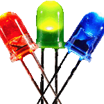
 LEDs are the model railroader’s best friend. Low power consumption and a wide variety of colors, sizes and styles make them the go-to lighting source for modeling in the 21st century. Even when you are looking for a distinctly “incandescent” look, LEDs can do the job better than a miniature incandescent bulb. In addition to single color LEDs, bi-color packages include two LEDs with distinct colors (red & green, for example), allowing the led to “change color,” useful as a panel indicator or signal light.
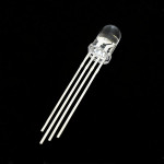
RGB LEDs are a three-led package that are intended to function like a display “pixel” and produce any one of 16 million possible colors. Theoretically, at least, RGB LEDs can meet almost any lighting need.
RGB LEDs require a microcontroller, such as an Arduino, to modulate the red, green and blue channels respectively via PWM. So while the upside of RGB LEDs is the huge range of colors they can produce, the downside is that a single RGB LED requires 3 pins on your Arduino. Ouch!
Addressable LEDS
A particularly elegant solution to the pin problem is to use “addressable” RGB LEDs. Addressable RGB LEDs (ALEDS from here on) are a special package that includes an embedded controller chip—I use the ones with the WS2812 chip because they operate at +5v. There are other WS28XX versions that do the same thing, with different specs, so different versions may not be compatible with each other.
The controller chip takes over the job of modulating the LEDs to produce the color set by an attached microcontroller. Data is communicated serially over one line (using only one Arduino pin), cutting your pin commitment down to what it would be with an ordinary, mono-color LED.
It gets better — the WS2812 also functions as a shift register, responding to its part of the data stream, and shifting the rest on to the next unit in the chain. Thus, a single data line (and still only one pin on an Arduino) can control multiple addressable LEDs wired in series.
ALEDS comes in a number of package styles, including both SMD and PTH types. Whatever package style, multiple ALEDS are wired together in series like so:
Only three connections are required to power and control the entire chain: VDD (+5v), GND and DI (Data In). Each ALED connects to VDD and GND, and has DI to receive data plus DO (Data Out) to send to the next unit (if any).
LED Strips
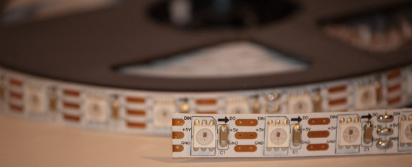
A particularly useful implementation of SMD style ALEDs is LED strips – available on reels in lengths of 1 to 5 meters. LED densities vary from 32 to 144 LEDS/meter (the higher the density, the smaller the LEDs themselves). I find the 60/meter type most broadly useful and easily obtained for about $20/meter from Sparkfun in 5 meter roll or a little less through Amazon though only in 1 meter lengths so far, or Chinese export sources, though specifications for those can be all over the map.
To control the entire strip, you connect to the first LED. The strip from Sparkfun comes with wires already soldered on to the first LED—here I’ve already removed and deployed the beginning section of a 5 meter reel.
You see, what makes these really special is you can cut them apart to use singly or in custom strips. Cut in the middle of the pads and you get this:
The soldering pads are small, but doable if you have a sharp point on your soldering iron; definitely easier than trying to solder an SMD chip itself. The LED unit seems well enough protected from heat when soldering to the pads so long as you don’t linger with the iron too long. To wire the data correctly, follow the arrow indicating data flow direction. Otherwise, the +5V and GND pads are rails that can be fed from either side.
Software and Usage Guide
Adafruit Industries calls these little devices “NeoPixels” and has developed a great Arduino library and usage guide. Download the Adafruit NeoPixel library package. They also have a broad array of NeoPixel products to work with, so I recommend you spend some quality time perusing their site. Sparkfun has two things Adafruit does not have — clear lens PTH types and bare 60/meter LED strips (no silicon protective jacket).
The WS2812 chip is sensitive to power anomalies, so there are some important rules to follow when using them:
1. Connect a large capacitor—I use 1000µf caps—across +5V and GND near the first LED. This helps buffer power surges. I use a regulated power source, but use the CAPS too just to be sure.
2. Place a resistor in the 300-500Ω range on the data line, near the first LED. I use a 1/4 watt 470Ω resistor.
3. Avoid connecting to live power; connect ground first if you must.
4. Avoid connecting the data line to a power (or signal) source before you’ve connected and activated +5V power. I’ve broken this rule accidentally to no ill effect; but it makes sense so I make sure power is on before any data is sent. If the same power supply powers both the ALEDS and your Arduino, you shouldn’t have a problem.
Sketch Basics
The Adafruit library comes with demo programs to get started with. To use the ALEDS your sketch has to first include the Adafruit library:
#include <Adafruit_NeoPixel.h>
Then you create the global strip object you’ll use to control the strip.
Adafruit_NeoPixel strip = Adafruit_NeoPixel(NUMBER_OF_PIXELS, PIN, NEO_GRB + NEO_KHZ800);
The strip is initialized (with all pixels turned off0 in setup() this way:
strip.begin();
strip.show();
Color values are unsigned 32-bit values derived from RGB values supplied to the Color() method of the strip object:
uint32_t colorvalue = strip.Color( R, G, B);
where R, G & B are values between 0 and 255, resulting in over 16 million possible colors. You can find out more about RGB color here.
In loop() you set pixel colors this way:
strip.setPixelColor(PIXEL_NUMBER, colorvalue);
where N is the number of LEDs in the strip, and PIXEL_NUMBER is a number between 0 and N – 1. Then call
strip.show();
to refresh strip and show the pixels when you are ready. Since this is a shift register device, data is sent serially, but the show cycle is parallel – all pixels change at the same moment.
To scale the brightness of the strip as a whole, you use
strip.setBrightness(X);
strip.show();
where X is a number between 0 (strip off) and 255 (full brightness).
That’s all there is to it. To see it in action, here is a video of a couple of light bars I’ve fabricated, running a little demo program that borrows a cool color wheel function from the Adafruit NeoPixel “strandtest.ino’ demo program.
Layout Usage Ideas
Being able to control all the LEDS on a control panel through a single data line is a great place to start. Multiple colors give you more ways to convey information through panel LEDS. It wouldn’t occur to me now to use any other type of LED in an Arduino-based control panel.
The smallest PTH type available appears to be 5mm, while great for control panels these will be about 24 scale inches in diameter in N Scale – a little large for most common direct lighting purposes; though they would work very well as a light source for fiber optics.
On the other hand, in N Scale, they are great for indirect lighting applications, such as providing interior illumination and lighting effects. For hidden light sources I favor the SMD style cut from a strip. Easy to glue in place and keep hidden.
I came across these when I was searching for a way to light my layout in its tight quarters. The light bars in the demo are the first two I made to try out my idea. As you can see from the demonstration, they are capable of producing a lot light; with enough bars there will be more than enough to light my layout and provide fun lighting effects.


I am very interested in using Arduino to control servos to move the points and an LED equipped control panel to display the position of 7 turnouts on a small switching layout I have built. I read your article “Running a Small Layout with an Uno”, but also read your article regarding ALED’s. This got me wondering about using a series of ALED’s instead of individual common anode LED’s on the control panel. I would be interested in your thoughts on this. Thanks for the great blog.
Hi Mark,
I think you are on to a great idea! ALEDS would give you some added flexibility in your control panel design (not to mention a vast selection of colors you can use). One of the things I like about ALEDS is the simple wiring: power, ground & data control the entire thing. Code-wise, the methods for manipulating individual ALEDS are uncomplicated, similar to the methods used on a shift register chain to control regular LEDS. So I would encourage you to give it a try. Best, Rob
Mark, any follow up on your thoughts?