
In Block Occupancy Detection for DC and DCC I demonstrated the use of an ACS712 sensor and an Arduino Uno to sense current draw across the rails, the basis for most block occupancy detection systems. Assuming that one has also equipped some rolling stock with resistor wheel-sets, lighting or sound decoders, so that the entire length of a train is detectable, the theory is that current draw indicates that a block is occupied — and lack of current draw indicates that a block is clear.
In reality, it may not be that simple if you have devices drawing from track power other than locomotives and rolling stock. Any background current draw on rail power can interfere with the current sensing model.
Rail Powered Accessories
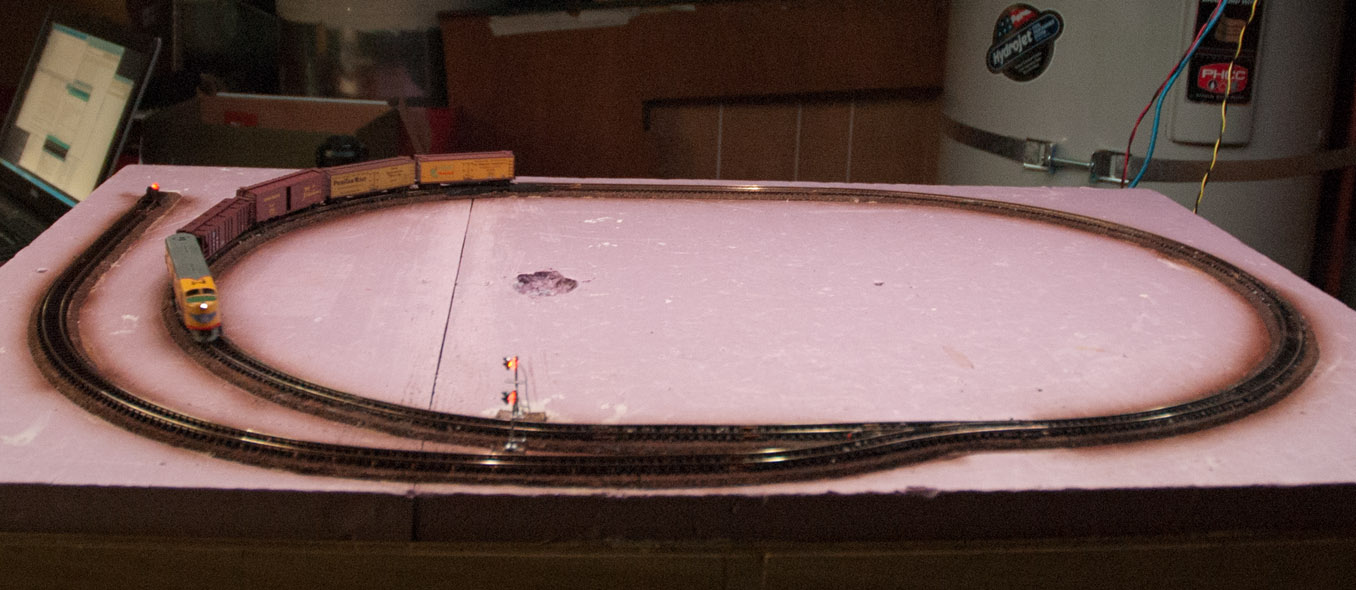
The Test Loop
Keen eyes will notice that the test loop has a rail powered light on the Atlas track bumper at the end of the siding. I laid the track on the test loop long before I understood block occupancy detection. I won’t do that again as I build the L&NC.
The problem is that the bumper light draws from the track itself and thus presents a constant load on that block. The draw of the lamp forces a slightly higher threshold for determining occupancy than would otherwise be appropriate. Static loads on monitored blocks greatly complicate current sensing.
The best practice where current sensing is used to detect block occupancy is to feed accessories from a separate power bus. To use track power (as you might with a stationary decoder running a turnout motor), draw from outside monitored blocks—from a separate branch or sub-bus—to avoid confusing the occupancy detection system.
Solving the Continuity Problem.
While current sensing works well on a DC layout, as shown in the first video demonstration, the use of current as a control mechanism means that block occupancy is undetectable at times because of normal operation. Similarly, any transient loss of DCC track power (as with a short) will throw the occupancy detection system off for the same reasons. I think of this as a continuity problem.
The solution in both cases is to monitor the track bus with an extra sensor and lock the state of the system whenever the track bus is off. The simplest algorithm, puts it a slightly different way:
if track current is flowing then check blocks and update else maintain current state
E.g. ( in C++, where “master.on” represents the master current status):
if(master.on == true) {
  for ( i = 0, i < NUMBER_BLOCKS; i++) {
    // check block sensor i and update block status
etc......
For the cost of a sensor and a few lines of code the block occupancy system will now maintain its state correctly whenever there is a total loss of track power.
Wiring for Detection
Preparing the test loop for the Arduino & ACS712 sensor based occupancy detection system was a bit of a chore, primarily because current sensing requires some rethinking of the standard approach to layout wiring.

Test Loop Wiring. Block sensors were added in Phase 2. Phase 3 signals and lighting were in progress when this picture was taken.
The test loop represents my first crack at it. Needless to say, there is a list of things that will be done differently on the L&NC.
Routing Buses
The loop has a bus structure that, except for the lack of the DCC command bus (I connect my throttle directly to the booster when it is attached to the test loop), is the prototype for the L&NC.
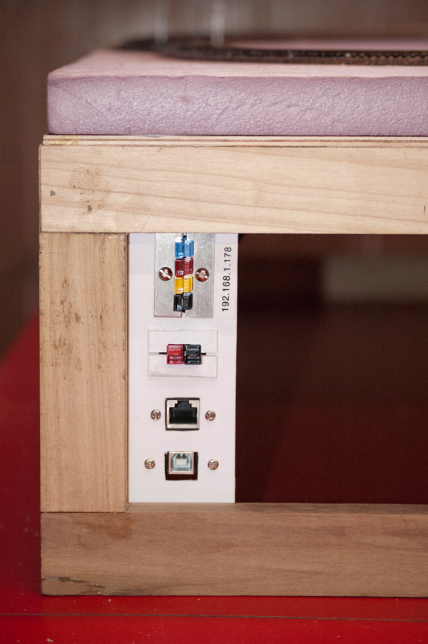
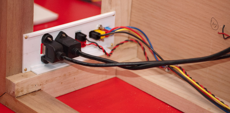
Test Loop Connection Panel
The bus structure begins with the connection points on one end of the layout, mounted on a connection panel made from .080 styrene sheet. Every module on the L&NC will have one of these, with matching cables at the opposite side where it adjoins the next module.
Starting from the top the first two connection groups are polarized power connections made with color coded Anderson Powerpole connectors. A “Recommended Practice” per the Ntrak Manual, these things are a reliable solution for creating polarized power connections. Some parts are available from Amazon; I find that Powerwerx.com has the best selection of PowerPole parts and supplies. The 15 amp gear should be sufficient for most N Scale layouts (an N Scale layout requiring more than that would be something to see!). Kudos to Ntrak for finding and adopting these connectors. BTW: the crimper is expensive but indispensable if one is going to make a bunch of Powerpole connectors.
The top group is the main DC power bus in three voltages: 12 (yellow), 5 (red) and 3.3 (blue) plus ground (black). This was also where I attached a label with the loop’s assigned IP address.
The next group down is the track bus (red & black); my DC power pack and my DCC booster can connect to the loop here with a matching plug.
The next two connections are an RJ45 port for Ethernet and a USB connection to the UNO. Both are assemblies I got from Adafruit Industries. On the L&NC, the USB port(s) for attached Arduino boards will be located in an accessible place, away from the other connection groups (which will generally be hidden).
Panel Bus Connections
Color coded power buses are routed along the edge to a central barrier strip where feeders take off to supply power where needed. On the L&NC I’ll choose different, unique colors for the track bus and feeders to reserve black for system ground and red for system Vcc (+5 volts DC).
Suitcase connectors are really popular these days for connecting wires without soldering. If you are not going to do occupancy detection then directly connecting feeders to bus wires with suitcase connectors is a clean solution. However, once you start down the road I’m traveling–whether your solution is off-the-shelf or homemade–suitcase connectors are not helpful. Instead, I find that PC board mounted screw terminals make easy wiring connections that are reliable and easily changed when necessary. When dealing with magnet wire, which you have to use in N scale if you want to run wires through scale light poles, conduits, etc., top-of-the-line PC board terminal systems are the ONLY reliable solution (the cheap versions will drive you crazy with intermittent connectivity).

ACS712 Board
The ACS712 sensor boards come with screw terminals for the monitored load, plus 3 pin headers that take standard 3 wire servo connectors for connecting to system power and the microcontroller. Wires that connect to the central barrier strip have crimped terminals. I mostly solder at the PC board level and, less often, to make special cables (I solder track connections too, but that is a different issue).
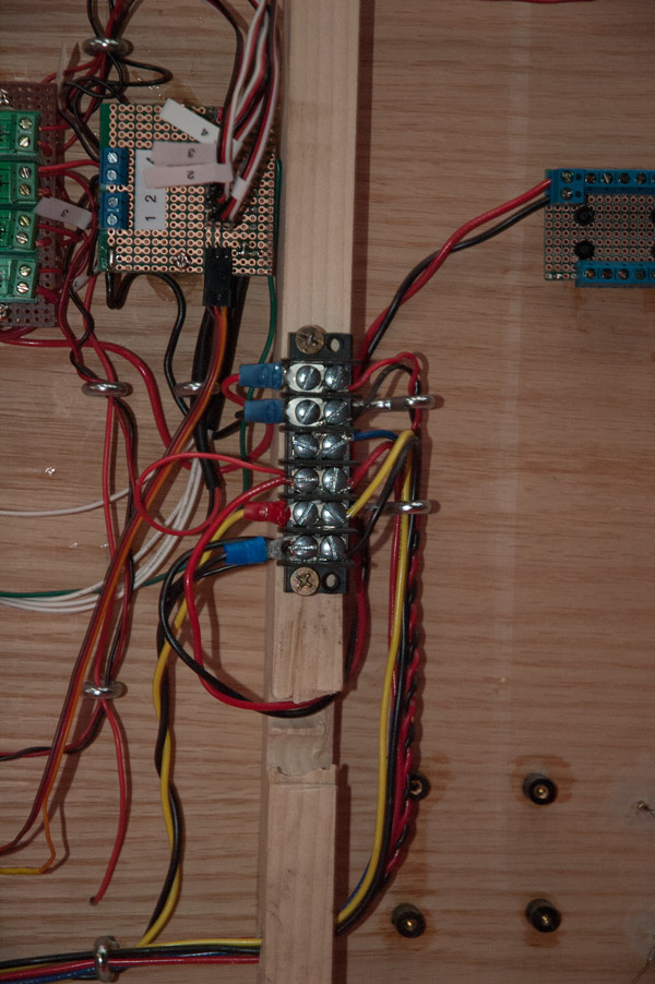
Power Distribution on the Test Loop. The board in the upper right corner is for distributing 5 volt power to the signal system via PC board terminals.
On an L&NC module, the bus will continue from the central distributions point out to the edge configured to connect to the next module. One big change in module construction on the L&NC will make wiring easier: the cross frame members will be pre-drilled with large holes. That “little” gouge you see where wires cross the frame member at the bottom of the picture taught me that lesson.
On the test loop the 12 volt bus supplies the attached UNO with its Ethernet shield; the 5 volt bus supplies all sensors and actuators attached to the UNO and is generally considered system Vcc. The 3.3 volt bus is not currently being used on the test loop (but would be great for low current lighting or animations). All share a common ground (really important!). NB: I use modified Computer power supplies that produce all three voltages at once with a common ground. Multiple DC power supplies can be combined to the same effect; just tie their grounds together to create the common ground.
Even on the test loop, the 5 volt bus is used so much that I need to create a distribution system to get power where needed. The lesson for the L&NC is I will need to have distribution nodes for the whole power bundle in a few strategic locations on each module. Obviously, I need to do some more detailed wiring planning in advance so I know where everything has to go.
Routing Feeders
Current sensing encourages a nodal distribution system for track power. Instead of attaching feeders to the nearest track bus, the feeders are routed to an area where the sensors have been mounted. You could mount individual sensors at the points where feeders descend from the tracks above. In some situations that may work better; in other situations, aggregating the sensors in groups is the easier and more effective method.

Current Sensors and Block Feeder Connections.
ACS712 sensors read only one of the two rail conductors. On the test loop sensors are attached to the red rail.
I tried to complete the rail feeder connection with a board (with terminals) across from the sensors for the black rail connection points. I also ended up using the same board to centralize the power and data connections for the sensors and the servo for the turnout. In the future I will not mix track / control system connection points in this way.
Block Occupancy Detection in Action
Here is demonstration of the progress so far, with block occupancy detection active on all 4 blocks of the test loop. The signals are programmed to respond to block occupancy and the state of the turnout (the turnout actually has three unique states: “aligned main”, “aligned divergent”, and “in motion”), allowing you to see the system responding as trains move along the track. You’ll see it work in both DC and DCC — the layout works whether a power pack or a DCC booster is plugged into the track bus port. I have yet to see a single commercial occupancy detection solution that moves as easily between DC and DCC as this one does. I added a station with internal lights (connected to the same nodal system that supports the signals) to give just a little hint of the capabilities that will be unlocked on the L&NC.
In future installments, I’ll dig into the occupancy detect code again to give more insight into how it works. I’ll also go into the details of how I’ve implemented signalling on the test loop, including some special (and inexpensive) gear I’ve designed to allow a single microcontroller to run up to 255 nodes of signals and other kinds of lighting or animation.
Thanks for this great article!
I will explorer OC detection based on your experiences on my layout.
Regards,
Kay
Glad you found this post useful. I hope you’ll share your experiences as you try this technique out.
I certainly will!
Besides the ACS712 5Amp modules, I have also ordered these “LM358 100 Gain Signal amplification module Operational Amplifier DC5-12V” modules off of eBay (for about a dollar a piece..).
I’m going to see if those will help to condition the signal a bit before going into the Arduino.
This idea is loosely based on this article:
http://www.instructables.com/id/How-to-Measure-AC-Current-using-Hall-Effect-Sensor/step2/Build-an-extension-cord-with-ACS712-Module-in-the-/
I already have a working Arduino based LocoNet circuit, so I will use your sensors as front ends to get OC detection back to JMRI
via LocoNet.
Thanks again for your work on this Robin.
Regards,
Kay
These little Arduino’s are really quite terrific, aren’t they?
Interesting. Let me know how that goes. It looks like it might be a good solution to signal degradation over long runs.
I’ve been thinking about a different problem altogether, which is how do you handle more sensors than you have analog pins for? The answer appears to be multiplexing the sensors with with a TI 4051 Mux/Demux. Combining the mux/demux with a signal amplication circuit would be a great way to address pods of sensors distributed around a layout (thus keeping track feeders short).
I would try and keep it simple Robin.
An additional Arduino Pro Mini costs almost nothing and will give you 6 more analog pins.
Or get a Mega for $8 on eBay, with 16 analog pins. Those Arduinos are so cheap now that
it seems easier to just add a couple to your layout when needed.
The ACS712 have arrived yesterday, and I hopefully will be able to run some tests this weekend.
The gain amps will probably be here in 2 weeks or so. Until then I’ll play around with your setup.
Regards,
– Kay
Hi Simon,
I set up a test track yesterday with a ACS715 5A and loaded your sketch to a UNO.
The readings from the ACS712 without being connected to the track where “Block occupied”.
I tried a different module and that on said “Not occupied”.
However, I then connected the ACS712 to the track and placed an Atlas GP40 on the track,
but it wasn’t detected. Only when I applied throttle the sketch detected the current change.
Have you ever tried a single engine or a single car with a resistor wheel set on your test track?
It seems to me that the ACS712 is way to insensitive to detect the small currents from a single
piece of rolling stock, car or parked engine.
Well, I hope that the gain amps will make this work. I’ll let you know.
Regards,
Kay
Patience, friend. I started in a similarly disorienting way, and for a while wondered if I’d get it working. I assume your loco is a DCC locomotive, so if everything is set right it should immediately be detected as soon as it touches live DCC rails. There is no reason to amplify the signal for a short run to an Arduino.
Let me suggest that you fill our the contact form so we can establish direct email communication. That will make the back and forth a little easier.
I have a third blog entry coming on block occupancy — this one devoted to software issues. That may be helpful. But in the meantime, send me your email address via the contact form and I’ll help you out.
Robin
Hi There,
I’m actually looking to achieve this very thing on my own layout (under construction) so I am curious to know, do you have to use the 5 AMP version of the ACS712 or will the 20 AMP version also work? The reason I ask is that I have a handful of the 20 AMP ones already, and while I will have to buy more, I wanted to make sure of whether this would work with the 20 right away so I can do my prototyping. I am using N Scale (just for reference) and I am familiar with needing to do resistor wheelsets, but I wasn’t sure how this will play into things since I am new to this approach.
Thanks for the great articles!
The issue with the ACS series is noise at the low end; the newest versions have made some improvements, but I believe the detection limit is still around 10 mA with the latest versions. The 20 Amp version will further limit detection because of the limited resolution of Arduino ADCs. With the 10bit ADC in most boards, your sensitivity will be mathematically limited to 20A / 1024 == 19.5 mA. It will work with locomotives, but you will not be able to detect resistor wheels.
You did not mention what style of control you are using: DC or DCC?
If you are using DCC or DC-PWM to control your trains, then you have a much better detection option: CT Coils. Low noise and extremely sensitive, CT coils can see a single 10k resistor wheelset on the tracks.
See Current Sensing and Occupancy Detection for DCC for a basic intro to CT Coils.
Best, Rob
Hi Rob,
I have implemented your DCC block detector on my HO scale layout, and I have an issue. I have been adjusting the variable called occupancy_threshold higher, because I was getting strange readouts of block occupied / not occupied, and it has worked for the most part but every so often I get a huge spike in current, and there is no train on the track. Am I adjusting this right? Feel free to email me back. Thanks.
Justin