
The Roundhouse / Turntable complex at the Red Bluffs Yard is the focal point of the lower level of the L&NC and one of the more complex projects planned for the layout. In the first installment (which is also step 4 of the build out of Module 1, lower level) I wrote about how I built the pit and bridge base, and showed the mechanism I developed for the turntable using Actobotics robotics gear. In this installment, step 5 ( Links to step 1, steps 2 & 3) of this module build out, we’ll take a look at the buildup around the turntable, adding track and integrating it into the scene. I’ll also talk about how I completed and wired the bridge. Along the way I took the time to install basic scenery elements while I have free access to this section of the layout.
Step 5
Finishing the Pit
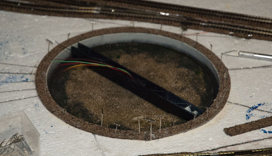
The first task after installing and leveling the turntable pit was to create a rim and cover the rough opening for the pit. After looking at a lot of pictures of prototype turntables I concluded that the rim needed to be around 4 or 5 scale feet wide. Rather than try to cut a circle out of styrene, or something like that, I elected to use a strip of cork roadbed. With the beveled edge against pit wall, and the square edge forming the outer edge of the rim, the look seemed about right.
One thing I found out in my research was that track rails are typically attached directly to the rim material (usually concrete) without ties. I decided not to model it that way because I just don’t want to get bogged down with gauging problems. So I elected to mount the ties to the rim so that they will keep the track in gauge.
Its not prototypical, but that’s OK with me because this is one of those places were functional reliability has to win out over prototypical niceties. As you can see in the picture below, I weaved the ties of the adjoining tracks between each other to achieve the correct track placement along the rim where it meets the bridge. Preliminary testing established that I’m getting good alignment and smooth wheel transits across the gap.
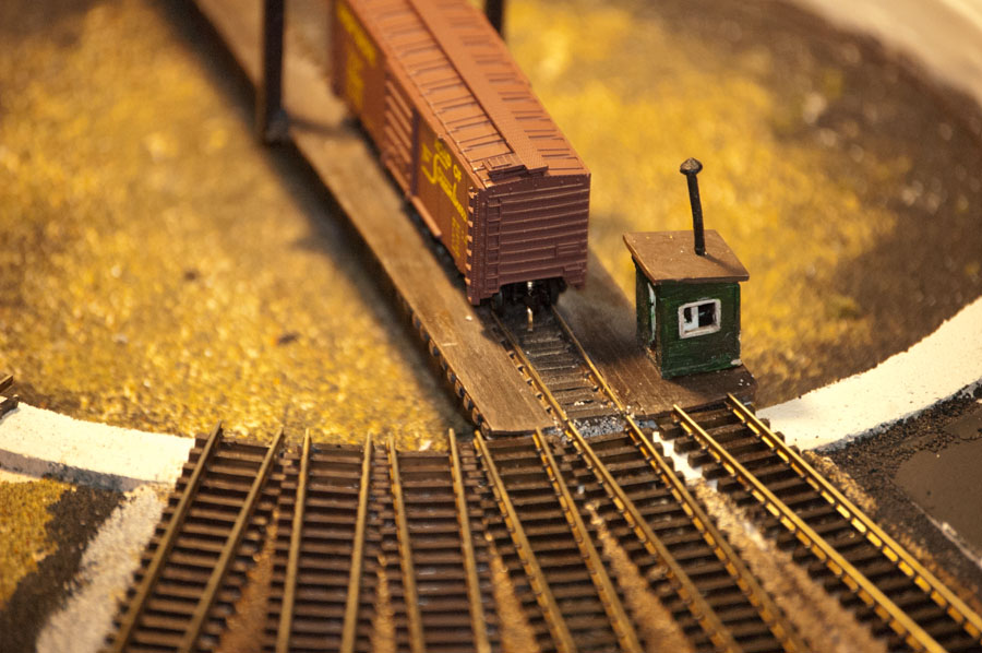
Track from the Roundhouse meets the turntable. Ballasting is in progress so there are bits ballast everywhere at the moment!
I painted the rim concrete to match the rest of the pit. The texture of the roadbed material is a little rougher than I anticipated. A second coat of paint smoothed it out more and left me with a surface that is a little worn from the effects of time and weather. I’m pleased with the effect; a perfectly smooth surface just wouldn’t be right.
Finishing the Bridge
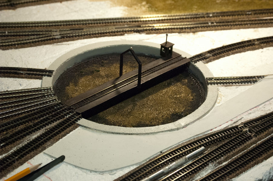
In addition to the powered track that also serves as a reversing section, the turntable bridge has an operators hut containing a warming stove with a red LED for creating a hot coals effect. The central arch–which prototypically was often a rotating connection point for the incoming power line to run the turntable–is outfitted with a simulated rotating beacon that will run whenever the turntable is in operation. Not even remotely prototypical, this little enhancement is just a way to animate and make the turntable even more interesting. I did say at the outset of this project that I was going to throw in animations at every opportunity!
I started the deck by creating a base frame to fit over the bridge and hold a piece of flextrack (I’m doing this layout in Peco code 80 gear).
Starting with the base frame, I continued adding cross-members until there was one in each space between ties. Then I decked it with .030 x .080 styrene “planks” cut to various lengths from scale 8′ to scale 32′, creating a plausible planking effect..
The central arch is fabricated from .080 square tubing. I added etched brass X-bracing in a scale 18″ size so that it would resemble beams fabricated from plates and X-braces. I thought about trying to fabricate brace & plate beams, but felt it would be a little too difficult to pull off and make strong enough for practical use.
The rotating beacon at the top of the arch is fabricated from three red micro SMD LEDS arranged in a triangle. The magnet wires (1 common anode and 3 cathodes) are connected to an incredibly small rotating beacon simulator board that I purchased from Ngineering.com. The have a nice collection of simulator boards geared to model railroading, with everything sized for N scale (these boards will work in any scale, so don’t be deterred if you don’t do N).
Actually I bought 2 because I ended up screwing up one of the outputs on the first one. These boards are smaller than a dime and soldering wires to them is tricky. On my second attempt I soldered short 30 gauge solid wire leads to the board (easier than soldering magnet wire), then soldered the 40 gauge magnet wire to the leads.
To answer the obvious quesiton, I could very well have done the rotating beacon effect with an Arduino. However, this little board is particularly good at that job, and I don’t have to use 3 PWM pins (plus the timing sensitive programming) to do the job. I can run this effect from a single connection on a Duino Node, simply turning it on when the bridge moves and off when it stops at its intended destination. This is good example of how one has to balance all the trade-offs when designing a system based on Arduino technology. Sometimes an external utility board gets you to the right place more efficiently than doing it from scatch.
The operator hut is made from a white metal “trackside shanty” kit by Stewart Products. I decided that the hut needed a little stove for heating, to go with the smoke jack provided by the kit. So I fabricated one from a piece of brass tubing and a styrene circle for a top. I cut an opening in the brass to serve as the front opening. A red led mounted in the bottom of the tube (not shown) will be used to create a fire effect that you will just barely see through the open door of the hut. I’ll produce the effect with PWM on an Arduino board instead of a dedicated simulator. So the turntable bridge will have two different light animations.
With all the pieces assembled, the wiring in and everything painted, it was time to connect all the wires to the leads from the spinner and attach the deck assembly to the bridge base. If you look carefully you’ll see a black object to the right of the center — that is the beacon simulator in protective heat shrink tubing.
Are those fishing weights attached to the underside of the deck? You guessed it! The white metal hut is rather heavy (relative to the weight of the styrene); the weights are needed to balance the bridge. The white object between the girders on the left is a nylon screw with a rare earth magnet (Neodymium, available from K & J Magnetics) glued to its head, screwed into a nylon nut attached to the bridge. That is for the position sensor reed switches I’ve previously described.
Scenery
In addition to finishing the turntable I am doing as much scenicking as possible while I have this module on its own on a work table. As I am doing this I am reaping a bonus from my modular design: the ability to take a module and place it on a work table for 360 degree access at chair height.
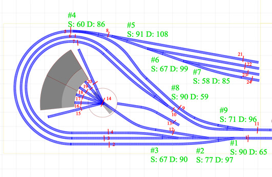
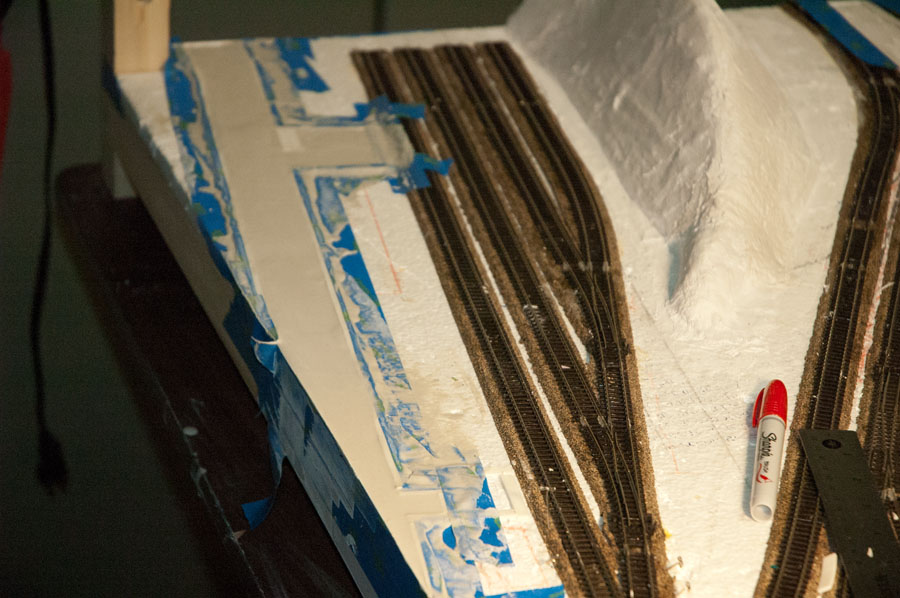
Referring to the drawing of this part of the layout above, I decided to add a small mountain in the space between the yard at the top and the two legs of the reversing loop at the bottom. This creates a view block that isolates the yard into its own little world.
I also decided to create a couple of roads using Woodland Scenic’s Road System paving tape and Smooth-It pavement material. The system works pretty well. I do recommend viewing their video tutorials for instruction in using the system, which you will find on the product pages.
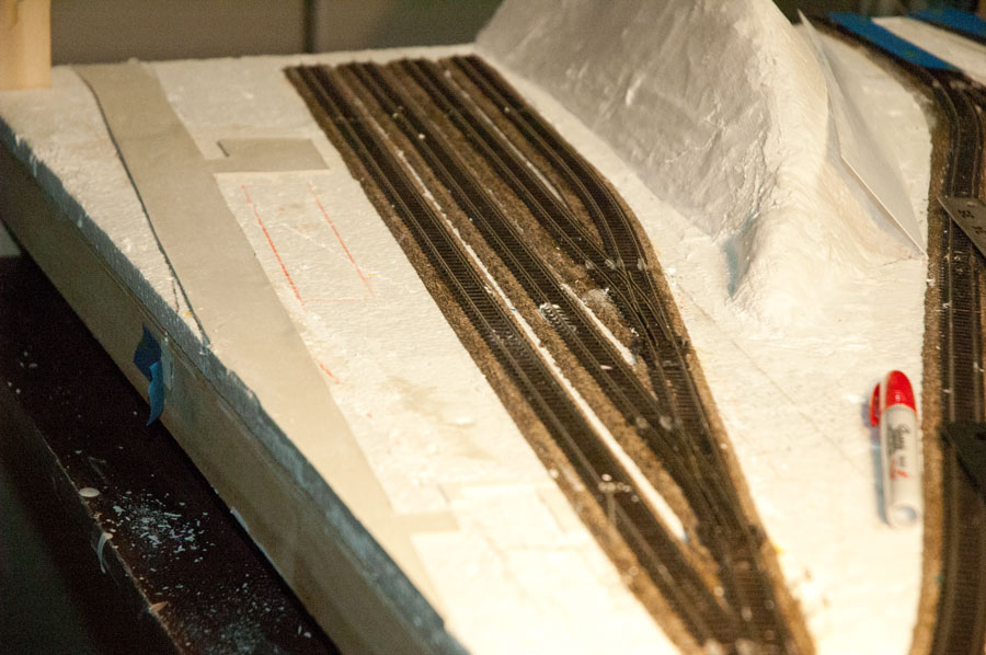
After removing the forming tape, you are left with this:
You’ll see that the road includes a driveway and parking lot at the top of the picture, and another driveway at the bottom that will lead to a gravel parking lot. These are provisions for future structures I have planned –a multi-unit rooming house for railroad workers at the top and a yard office at the bottom. I also created a road on the opposite side of the module, running between the legs of he reversing loop as an access road to the roundhouse / turntable complex. I figure the employees need some way to get to and from work!
The mountain was made from several layers of foam insulation glued together then carved to a rough shape. I glued the foam shape to the layout, then covered the whole thing in plaster cloth. Then I selected some rock molds and cast a few rocks. After gluing the rocks to the mountain (Attach rocks with wet plaster? Forgetaboutit! Liquid Nails for Projects makes attaching hydrocal rocks to another surface a snap, with its strong tack and immediate hold), I filled holes and blended the rocks into the terrain with Sculptamold. I painted everything except the rocks the medium tan I’m using as a base color, then painted the rocks themselves with a combination of iron oxide and earth tones. I glued down some earth blend and other ground foams — and, voilà, the red bluffs were born.
What’s Next?
More scenicking, of course. But it is getting to be time to go underneath the module again and install more of the electronics, including controller hardware for the 9 turnout servos and the controller package for the turntable / roundhouse.
Until then, happy railroading!



One thought on “Adding a Turntable to the L&NC, Part 2”