One of the casualties of 15+ years of moving box storage was a Walthers (Heljan) Union City Roundhouse with 6 bays. No longer in the catalog, this was a really nice brick structure with a little extra decorative masonry, as might have been built in a prosperous town in the early 20th century. The “modern” roundhouse models widely available today are more shed-like and (to my mind, anyway) less elegant.
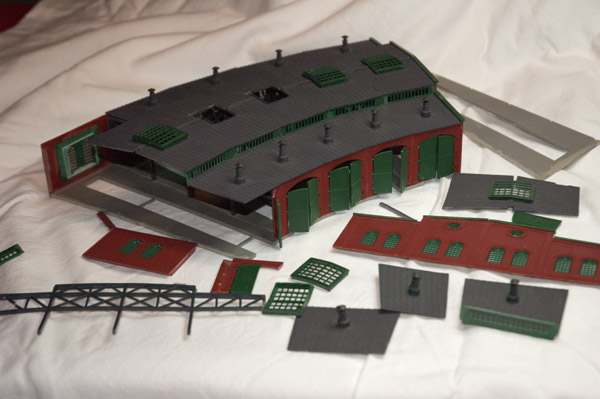
Roundhouse in pieces
The damage could have been a lot worse; mostly it came apart at glue joints. A little breakage, but not much. I originally built this twenty years ago as an exterior model; no interior lighting or details. It was nicely enough colored that it worked well unpainted (though I intended to get to that…. some day). No anti-crazing glue was available in those days, so the windows which look fine on the outside look atrocious on the inside.
Decisions, Decisions
The model did not have the common decency to completely disassemble itself, which would have made this much easier, so I had some choices to make. In contrast to the glue joints that failed, the rest were showing no signs of giving up easily.
First and most obvious was whether to rebuild the 6th bay, since most major pieces were intact. For the sake of the space available on the L&NC, cutting back to 5 bays makes sense without diminishing the impact of this model. I could have gone to 4, but the broken frame for the 5th bay door presented a nice weathering opportunity, which we’ll see later.
Secondly, what kind of lighting and how? I was thinking incandescent, and hanging lights would be authentic, so some sort of hanging lamp with an industrial style shade seemed like a good idea. I found both led and incandescent options; I decided to try the incandescent type.
Getting Started
Removing the floor turned out to be the easiest way to open up the model, so I decided to reconstruct the model with a solid top structure that is removable from a separate base. Putting aside the floor, I reassembled the top structure, leaving one roof section off where I planned to route wiring.
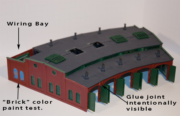
Main structure, partly reassembled
That decision, along with the intended orientation on the L&NC, spawned a few other choices. Now, when in operation, the interior will be viewable primarily through the doors and secondarily through the windows and skylights. Since the most open sight line will be through the doors toward the back, I decided to attempt some improvement of interior finish along the back wall.

Painted Interior Window Castings
I pried off the clear styrene, which was as difficult as I would have expected, requiring some grinding and sanding to get rid of stubborn bits holding on to the green window part. Then I painted the window part brick, leaving muntins and a thin window frame green. Having done the back wall I re-evaluated the other sight lines and concluded that removing the glazing elsewhere was probably not worth the trouble (I’ll keep that option open for later).

Light coming through simulated glass.
Since the glazing was gone, I decided to try using Testors Clear Parts Cement & Window Maker to make ‘glass’ in one pair of rear windows. It was easy enough to do if you follow the instructions, and the effect is interesting. I probably used a little too much, but the material seems to have a lens effect in windows this small. This simulates older glass nicely, but does not create a “see-through” window (for purposes of viewing the interior). The way the Roundhouse will be oriented on the L&NC, the back window will face a blocked (by the furnace) area, so you will not be able to directly look through these windows in any case. So I think I will do the rest of the rear windows the same way.
Paint Cheapskate
Model paint is notoriously expensive (over $5 per oz, discounted) and, frankly, nothing special beyond formulating specific colors that duplicate prototype colors. In this respect I’m lucky there is no convenient hobby shop here; that has forced me to look to other solutions which, to my delight, are vastly cheaper.
Liquitex BASIC Acrylic Paint (available at all major art/craft store and on Amazon), at $5 per 4 oz tube (cheaper in even larger quantities, or sets) is a good deal. It is available in a wide range of standard artists colors that are easily mixed to create any color you want (just keep track of the formula!). These are formulated for general artist use so they are thicker than standard model paints. I mix small amounts of paint with acrylic thinners to get whatever consistency I want.
My brick color is a simple mix of 50%Red Oxide and 50% Burnt Umber. My color for light colored mortar, masonry, stone and concrete is Titanium White with 5% Yellow and 5% Grey (a 50% Grey) – basically a dab of each into a larger amount of white.
Installing Lights, Round 1
I found some Miniatronics parts, counter-intuitively called “Lamp Shade with Bulb,” that I thought would make good hanging lamps for the interior, so I bought 10 of them from Hobbylink.
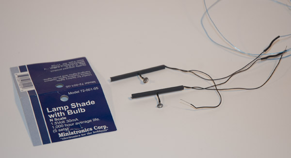
Miniatronics ‘Lamp Shade with Bulb”
Here two are mounted in 1/8″ Styrene u-channel that has been painted Floquil Weathered Black (from my limited collection of old paints) to match the interior girders. To size them, I studied the interior clearances relative to locomotives and realized that clearance was limited in the tall section, and non-existent in the shorter fore and aft bay sections.
Hanging Lamps in Bay 1
My feeling at that point was these lamps were not suitable for the short sections, since they would not be visible mounted up against the ceiling. That feeling increased after mounting and lighting the first pair.

Miniatronix Lamp Shade with Lamp – Lit
I guess I should not have expected much from a 1.5 volt 30mA lamp. Still, I’d hoped it would cast more light than that! As a decorative lamp it works fine at N scale – you get little peaks of them if you look in and they seem right. For casting light on the broader scene, even if I doubled up on them, another solution is needed.
Addressable LEDS
I’d already been working with Addressable RGB LED strips as a solution to bringing light to the layout, and it occurred to me that adding ALEDS as a hidden light source would allow me to more fully light up the interior. So that is what I did.

RGB LEDS for General Lighting
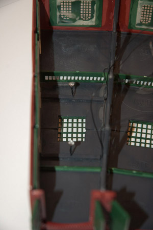
The individual pads are cut from a 5 meter strip and wired together with 30 GA wire. As you can see from the picture of the completed interior below, there are 10 of them with addresses 0 to 9.

Soldering Addressable LEDS
To solder the very thin wire to the pads, I taped the leads down and slipped the pads underneath. That was more than stable enough to make the soldering fairly easy. This particular LED is #0, so the left hand leads are heavier (22ga) for incoming power and data (for durability and handling), and the right hand leads out to the rest of the strand.
I fabricated the strand in two halves with 5 LEDS each, soldering leads from the two halves together during installation. Each half strand had to be carefully threaded through the girders. I did break – and repair – a couple of connections the first time I tried. After I got them threaded successfully, I glued the pads down to the styrene roof with dabs of Liquid Nails for Projects (low VOC, foam safe). You can bet I tested the lights before gluing them down!

Completed Roundhouse, from below
The LED wiring is simple and efficient – 1 connection to a digital pin on the Arduino, plus 1 wire each for power and ground. The incandescent lamps were more complicated since I had no intention of giving over 10 pins on the Arduino. Further, turning them on and off individually was not necessary, so I decided to run them in “bay pairs.” Unfortunately, the 60 mA draw of a pair of these is more than you want on an Arduino pin, so that meant some sort of relay or transistor would be necessary to switch the current.
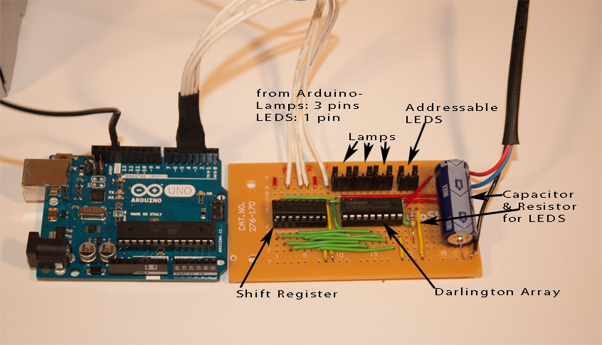
A Shift Register and a Darlington Array
Current isn’t the only problem: there aren’t enough digital pins on an UNO to control everything I have planned. So a pin preservation strategy is called for.
I decided to use a 74HC595 serial-in-parallel-out shift register. One data pin plus two timing pins (total of 3 pins) allow an Arduino to control 8 digital outputs; additional shift registers can be wired in series to extend the total number of outputs available without additional Arduino pins. The parallel output of these chips means that after the Arduino sends instruction bits serially, all the outputs are turned on or off at the same time (parallel output), a useful property for animation and lighting control.
Because of the higher current (and also different voltage) of the lamps, I put a UNL2803 darlington array — a transistor array that can sink high current — between the shift register and the lights. The only downside of a darlington is some current loss.
Both chips are inexpensive, running about $.60 each in small quantities at digikey. Now that I’ve worked with them I’d say they are very useful basic parts for the Arduino enthusiast.

Power Distribution to Lamps
I fabricated a little circuit board for the roundhouse, to join the “bay pairs” together and provide a 1/8 watt resistor for each lamp to be able to run at 3.3v. The darlington array sinks current rather than sourcing it, so the circuit is a common anode (common power) with the resistors and control on the ground side. Works fine. The circuit board was cut from a standard Radio Shack pre-etched PC board, and fits into the wiring space in the back of the Roundhouse.
I fabricated another board–version 1 of what will become a standard, chainable shift register board for layout control (but about half the size of this one) — to be mounted under the roundhouse base, it interconnects the two ICs, taps into layout power, connects to an Arduino and connects to the structure above. The board uses +5v power for logic and LEDs, and +3.3 for distribution to the incandescent lamps.
Roundhouse Controller with an Uno
The roundhouse board has an unused connector that would allow 3 more +3.3v lights to be added. I’ll probably use that capacity for some lighting outside the roundhouse structure when it is mounted on the layout, but I haven’t decided anything yet. That, by they way, is part of the essential elegance of the Arduino way; so long as a connection pin is available, adding more lights or functionality is as easy plugging things in and modifying your software to use them.
Here is a video tour of the project and demonstration Roundhouse lighting!
The sketch loaded on the Uno is different enough from previous examples, that I will cover it in Roundhouse Rebuild Part 2.
Loved the article on the Arduino controlling the lights in the roundhouse, I just started working the this item and I like it a lot. I could not make out enough details for your homemade PC circuit boards you made to add to the Arduino Power Distribution to Lamps & Roundhouse Controller with an Uno. Can you send me a wiring diagram you added and a component listf these two components
Hi Charles,
The board I created for this project is a hybrid that contains two unrelated sections (except for shared power feeds and ground).
One section — the right hand side — supports the addressable RGB LED chain, and consists of the power/ground feeds and a single data line. In terms of parts, the only special components are a 1000µf capacitor placed across +5v and Ground, and a 470Ω resistor placed in-line on the data line. Both components serve to protect the WS2812 RGB LED chip from power anomalies. For more on using WS2812 RGB LEDS see An Introduction to Arduino & Addressable RGB LEDs.
The left hand section is an implementation of a SN74HC595N shift register plus ULN2803APG darlington array [links are to digikey.com product pages] control device. This particular combination allows 5v TTL Arduino logic to control devices in a common-anode circuit where the devices can run at any voltage up to the 50v maximum of the darlington, and handle current up to 500 mA per darlington output. In the roundhouse project that allows me to run the hanging lamps at 3.3 volts while all the logic is standard 5 volts.
My first advice to anyone starting out to use shift register circuits is that you do the Shift Out tutorial on the Arduino site. This is the best way to learn the basic principles of wiring and using shift registers, whether using only one or creating a chain of multiple, interconnected shift registers.
Adding the Darlington Array is as simple as — using the tutorial as a frame of reference — connecting the outputs of a shift register to the inputs of the darlington, then connecting the darlington to the cathodes of target LEDS or other devices (instead of the anode, as you would if directly connecting a shift register).
That said, the mechanics of connecting a shift register to a darlington is messy because the pin distribution / order is different. The net effect is that no matter what you do you are going to have connections crossing each other which is a bit of a headache on homemade boards. In the example above, I arranged to two chips linearly, so that most shift register outputs (except output 0) and darlington inputs are on the same side of the board and are interconnected with the green jumper wires you can see on the lower side of the board.
Basically, using the shift out tutorial to understand where ground and power connections for the shift register go, connect the outputs of the shift register (numbered 0 to 7) to the inputs of the darlington (again numbered 0 to 7) and (with power, which can be different from 5v logic power, and ground to the darlington), then connect the darlington outputs to destination cathodes.
Note that in this project, there is a small second board that is inside the roundhouse to provide wiring points and current control resistors. Today I would put the resistors on the same board as the logic and just run a wire to the final destinations.
Today, in addition to including current control resistors on the logic board, I would arrange the chips side by side, so that the board looked something like this:
Notes about the design:
1. U1 = SN74HC595N shift register
2. IC1 = ULN2803APG darlington array
3. C1 is an optional capacitor if you get flashing when updating the shift register. See the Shift Out Tutorial for more information. I have yet to use a capacitor so I omit it from the circuit. I’ve retained it in the drawing for consistency with the Shift-Out tutorial.
4. Bottom 3 pin connector on the right side (your choice of connector hardware, or direct wiring) a) V++ power for your devices, on the roundhouse that’s 3.3 volts, b) Vcc 5 volt logic power, and c) common ground for both.
5. Middle 3 pin connector is for the three logic lines from the Arduino to the shift register; CP = clock pin, LP = latch pin, DI = data in.
6. Top 3 pin connector is the optional logic out to connect to the next shift register in a multi-shift register chain. Omit it if not creating a chain.
7. Resistors on the left are specific to your devices and the voltage you will run them at; the terminal block is a generic connector to your ultimate devices, with the common anode power available from V++ at the bottom.
8. Orange circles (instead of the green ones) are all connected to the common ground — wires are not shown for that.
9. To convert my design to the linear style I used in the blog post, arrange the two chips so the orientation mark end of one abuts the unmarked end of the other. For instance, move U1 to below IC1, which puts U1 outputs on the same side as the IC1 inputs.
10. To do a side by side implementation as in my drawing, use both sides of the board for the jumpers — for example, you could have the gold wires on top and the orange wires on the bottom.
For prototyping boards I use Busboard Prototyping Systems products, available on Amazon.com and elsewhere. BR1 would work well with a linear design; POW3U would be good for the side-by-side design. Remember you can always cut down a prototyping board to make the size reasonable for your application.
Hope this helps.
Thanks for taking time to share your marvelous Union City Roundhouse? I had looked at other roundhouses by Kato, TomiTek, Atlas, & Walthers. I even bought a few & then returned them. They are totally oversized for N scale. You Union City one is not, it’s perfect. So I started searching, & finally found one & bought it. I’m using Unitrack. It’s simple enough for simple me to use on my layout. I bought tracks with a pit, for the roundhouse, but I need to elevate the roundhouse & trim the sides of the track in order to fit the tracks in the stalls. I noted you appear to have added a thin base under the floor, & that would solve my problem. What did you use? Thanks
The base is a 1/2″ large cell Styrofoam sheet (glued to a plywood substrate) I bought at a home improvement store — the product is used as a barrier layer under the outer sheathing of a home. I just fastened the model base to that with some latex caulk. The turntable was a little more difficult to mount and align!
Best, R
Thanks Robin. What I was specifically looking at, was at the bottom of the plastic wall of the roundhouse. Where the red of the siding ends, there appears to be a 1/8 of grey material, which I assumed you might have used to elevate the floor of the roundhouse so the tracks inside were at the same level as the tracks entering from the turntable. I was guessing it might be a 1/8 in thick sheet of Styrene plastic trimmed to match the roundhouse floor plan. Not so? Thanks again!
That is the plastic model base that you see (5 of 6 sections from the original model). The structure is fastened to it with non-drying scenery glue so it is removable. R
Oh okay! Thanks!
Steve