
Since the test loop project is a dry run for a couple of key methods I expect to use on the new layout, I decided to start with a little formal planning using CadRail from Sandia Software. Years ago I tried an earlier version of their product and found it difficult to use. This time I did much better. The current version, for all its CAD power, is really pretty easy to use for basic planning. I downloaded the demo, spent a few hours doing the tutorial, and was able to produce this simple plan for a 2′ x 3′ test module in short order.
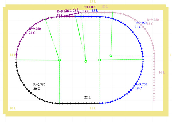
Track Plan for the Test Loop.
Not much to it: a loop, a turnout and a spur. I had not purchased the product yet so I didn’t have track and structure libraries to work with; everything was done with the general features, tools and components. The color coding is to indicate wiring blocks; essential to using the test loop to work out block detection and other technical issues.
When I then laid the track I was able to replicate the plan exactly, down to the too-close clearance (to the edge of the module) at the turnout. I could have shifted the whole thing during build to improve the clearance but on this occasion the point was to reproduce track plan exactly as drawn without significant adjustments; and to see how it turned out. No surprises.
I had CadRail show the radius points for each curve on the plan (one of many view options). Locate the radius point exactly on the layout surface and, using a compass, you can draw the correct track centerline exactly where it is supposed to be. You can print a plan with grid lines and dimension measurements to help transfer the plan — if you want to sacrifice a lot of paper to the cause, you can even print in real size. Having struggled to transfer hand drawings with dubious calculations to real world materials in the past, this is a definite improvement. At $79 to download the full software and libraries, it’s a good deal (for a bit more you can get a printed manual and CD-ROM installation disk, with a few extras to sweeten the deal. I went ahead and purchased the full monte).
Here is a view of the foundation for the loop.

It is a simple box frame, 2′ x 3′ x 8″, made from 1 x 2 and 2 x 2 poplar, with a 1/4″ oak plywood top (all from Lowes). In the past I’ve used common pine for benchwork. I chose hardwoods this time because I suspected they might work better for a modular system than softwoods, especially since I am trying to thin down the structure as much as possible while stiffening it as much as possible. Hardwoods are generally more dimensionally stable than low grade pines, especially in the smaller milled sizes. Furniture grade pine is good, but still not as strong as hardwoods and hard to get in my area. Hardwoods cost more, but for a small layout that extra cost is negligible. Poplar in the two sizes I’m using runs about $1 per linear foot, and is easy to work with. [Some poplar products are marketed as Sustainably Produced. I don’t know that is true with all poplar products.] The payoff is how much easier it is to keep your woodworking thin, straight and strong.

Corner Detail
I created a box frame with a top, not a fully enclosed box or box beam. The joinery is simple lap joints with some mitered joints at the corners; nothing fancy or complicated. Brads held the frame together while the glue set (the classic Norm Abram technique.). I included a reinforcement bar under the plywood top; It is not absolutely necessary on a box this size though it did contribute to getting everything square and flattening the plywood.
I topped the plywood with 1 inch insulating foam. The resulting structure is light and amazingly stiff. You can’t twist it easily; you’d have to push it past the breaking point to deform it. This is pretty much what I had in mind. I’m hoping that a substantial hunk of foam under the track will help suppress the mechanical sounds of locomotive mechanisms, which are not the sounds I really want to hear.
Finding a source of foam was more complicated than I thought it would be. The insulating foams sold for building purposes have changed over the years. Most are now faced with foil, paper or other additional materials. For my purposes, those extra materials are not useful. Then there is the whole problem of transporting 8′ x 4′ sheets of foam strapped to the top of the car and subject to easy damage.
Turns out that Owens Corning produces an unfaced foam product that is geared to the hobby market.  It’s a dense foam that resists compression and holds pins very well. It comes in easy to transport and use 2′ x 2′ x 1″ squares. The only source I’ve found for it so far is The Home Depot, where it costs $5.48 per square as of this writing. I thought that was pricey at first and, compared to a full 8 x 4 sheet of building Styrofoam, is it is. But compared to hobby specialty foam products, it’s very reasonable at less than $1.50 per square foot for 1 inch thick stock; and I can get it locally.
Building with foams presents several new challenges. At the top of the list is finding adhesives that are foam-safe. Many caulks and adhesives will attack foam. Secondly, since I am joining dissimilar materials in many instances, the caulk/adhesive has to work with all materials being joined. Porous materials are usually easy; non-porous materials like most plastics are more difficult. Needless to say, I spent a fair amount of time at both The Home Depot and Lowe’s reading labels.
For adhering foam board to plywood I selected Loctite PL300 Foamboard Adhesive. This product is primarily formulated for adhering foam insulation to basement walls and the like, so once it takes hold it is strong.

I used about 2/3 of a tube to adhere two pieces of foam to the plywood; I think I can use less next time. Initial grab is mild, giving plenty of working time, but also requiring some sort of strategy to hold the foam in place until the product sets. I tried both clamping and screws: a few bugle-headed screws proved the best method for anchoring the foam while it set. I had a mild warp in one piece of foam that I easily straightened in the process. The holes can be filled or used for something else later.
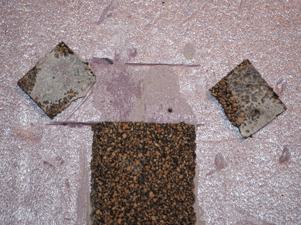
Trim and peel test.
 Next I had to adhere cork roadbed to the foam surface. I bought some Liquid Nails for Projects then did a quick test to compare it to ordinary white glue. White glue will adhere to the foam, but it’s a weak bond easily broken. Liquid Nails provides a much stronger bond. As tight as the bond is, the adhesive does not dig into the foam so I could trim and peel off excess roadbed after the adhesive set without significantly damaging the foam.
Here is a view of the top, with the cork roadbed down.

Next up, laying some track, installing feeders and powering up the test loop.
2 thoughts on “Building A Test Loop”