
This is the third installment in a series about the build out of Module 1, lower level of the L&NC. Step 1 was to install the basic wiring trunks and connection points, create track power distribution nodes then connect track feeders to the nodes. In Steps 2 & 3 I tested and corrected the track installation and installed servos at each of nine turnouts. Step 4 on this module is to install a turntable.
In this installment I will be introducing my fellow model railroaders to Actobotics system of robotic parts and supplies. If you are interested in creating kinetic components for your layout or diorama, you want to know about Actobotics.
Where are the Kits?
The plan for the L&NC has included a turntable since the earliest iterations. After all, what good is a roundhouse without a turntable to go with it? Way back when I bought the roundhouse (in the 90’s), Walthers also offered a 120′ turntable kit in the Cornerstone series. I had one at one time, but it did not survive multiple moves.

Roughed In Turntable
When I went looking for available kits and materials, the old Walthers kit was nowhere to be found and that there were few other choices in N scale. A new motorized turntable kit in N scale from Walters is due this fall. It looks like a good kit—with an additional module it is USB controllable —but at $349 list price it is unaffordable for my project. In any case, it was not on my radar when I started thinking about turntables. The cheaper Kato, Bachmann and Atlas motorized kits are a little too toy-like for my tastes. As to unmotorized turntable kits, there are few choices in N and nothing in the 120′ class that I need to fit the roundhouse.
So I was going to have to do this from scratch. Exactly how that would be accomplished was a mystery.
The Pit
I always figured I could fabricate a bridge; but the pit looked like a problem only an injection molded plastic kit could solve.
But then it occurred to me that I could make a pit with a plywood base (same 1/4″ material as used to deck the layout frame) and styrene strip material to form the sides.

Building the Turntable Pit with Styrene Strips glued to a plywood base.
Using circle cutting and plunge routing attachments for my Dremel, I cut a 9″ plywood circle out of the base material I had on hand. I cut some .020″ styrene sheet into strips about 3/4″ wide.
I started by adhering a course of styrene around the edge of the plywood circle with medium viscosity gap-filling CA. After the first course was complete and the CA set, I laminated two additional courses of styrene to the first one to build up the thickness and rigidity of the pit wall.
The circle cutter left a tiny brad hole at the exact center of the circle, making it easy to cut a centered 1/2″ hole with a Forstner bit. Why 1/2″? Because that is the outside diameter of a standard Actobotics bearing for 1/4″ OD tubing. A Forstner bit is precise enough that the hole will snugly hold an Actobotics bearing without glue or mechanical fasteners.
The Bridge
The basic bridge structure was an easy bash from two Micro Engineering 80′ Deck Girder bridge kits.

Two 80′ bridge kits provided all the material needed for the basic bridge structure.
One kit provided the center section of the bridge girders; the other provided material for four tapered end pieces required to complete the girders. Both kits contributed cross pieces. I found a set of pdf drawings of a 60′ turntable and used that as a guide to creating my bridge. After the basic bridge was assembled, I added a support plate with a 1/4″ hole to receive the top of the 1/4″ OD brass tube I’m using for the main drive shaft.

The assembled bridge, including the shaft support plate in the center. The prototype plans are for a much smaller turntable, but were helpful nonetheless.
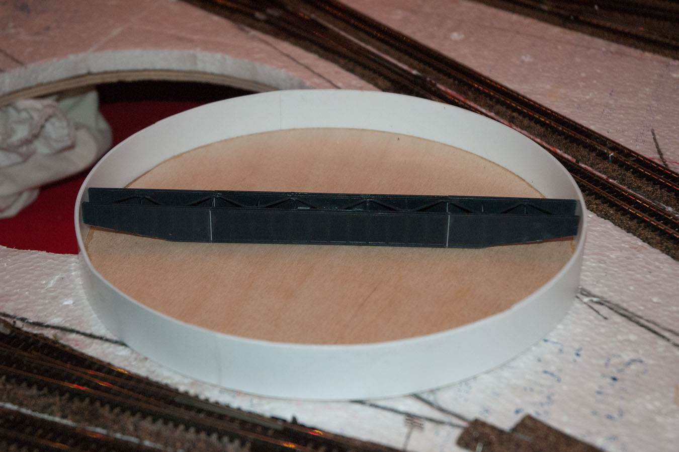
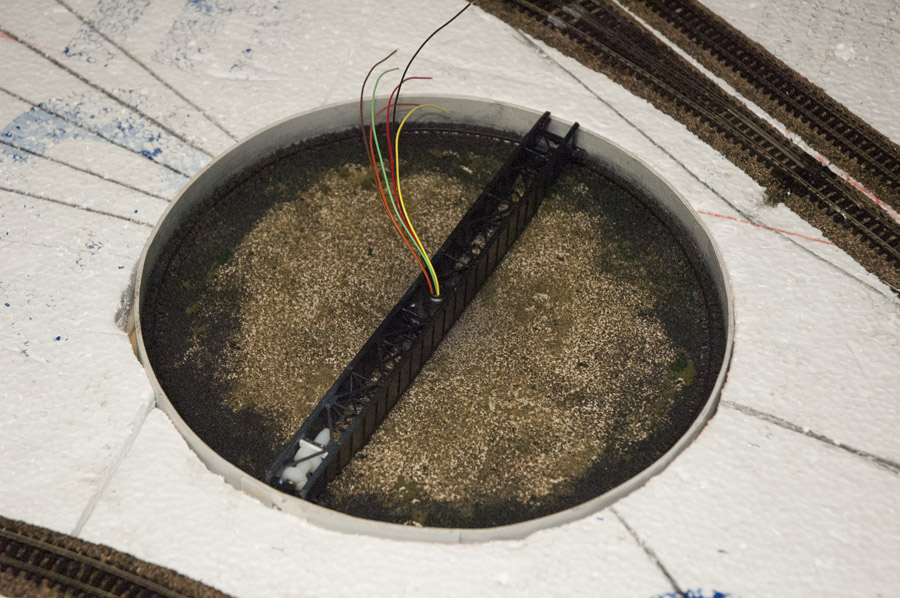
Checking the fit of the bridge in the pit.
The Mechanism
My original concept for moving the bridge was to directly attach a small stepper motor to a shaft extending through the base from the bridge. A small 400 step (per 360 degree rotation) motor looked promising but there was no way to run wires up the shaft. Same problem with using a servo—most hobby servos are limited to 180 degrees of rotation because of position sensing; servos without stops and position sensing gear can rotate 360 degrees. But servos without position sensing are not useful where accuracy matters. For precision, a stepper motor is the way to go.
To feed wires down a hollow shaft center for bridge track power and other purposes I have to offset the motor from the drive shaft. That necessitates a geared drive; but also creates the opportunity to to increase the positioning precision. So I started looking at off-the-shelf robotics gear.
I quickly homed in on Actobotics products available from ServoCity.com and Sparkfun.com. Its a very versatile line of structural and mechanical parts with standardized sizing and mounting patterns.
Great Stuff, but you’re on your own….
Unlike a lot of electronics gear for Arduino, Actobotics products do not come with tutorials. One useful exception is Sparkfun’s video on stepper motor mounts which helped sort that out. Otherwise, its a struggle for a newbie to know what parts you need to get started, much less how they work best together. It doesn’t help that model railroading is not on their list of standard applications!
In the end I simply had to buy a bunch of plausible parts and try putting things together. A few orders later I figured out a mounting and gearing arrangement that works, and can be easily replicated by anyone who cares to try.
The Parts
-
Actobotics Channel
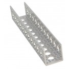
Channel. The physical core of the Actobotics system are the channels and extrusions from which structures can be created. Aluminum channel comes in a range of lengths—from 1.5″ to 48″—pre-punched with holes that match the standard mounting patterns used in the system. I chose a 12″ channel to serve as the “spine” of the turntable structure to hold the pit, the mechanism and providing the means to mount the assembly to the layout.
-

Stainless steel ‘D’ shaft.
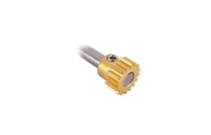
Shafts. Shaft sizing is tricky because it determines what parts can be attached to the shafts. 1/4″ OD turned out to be optimal for what I need. For the hollow drive shaft connected to the bridge I’m using ordinary 1/4″ brass tube. Actobotics products are precision milled; ordinary 1/4 brass tubing is not—it tends to be slightly oversized. To size the drive shaft I chucked it into a drill and, while running the drill at a low speed, used 800 grit emery paper to slim it down to 1/4″ OD. In addition to the bridge drive shaft, I needed two solid 1/4″ D shafts to form a drive train transmitting motion from the stepper motor to the main drive shaft. Sizing was tricky; it took some trial and error to get the desired results.
-

Bevel gears.
Gears. I settled on an 80 tooth hub gear for the drive shaft. It is driven by a much smaller 16 tooth pinion gear, providing a 5:1 gear reduction, implying a minimum positioning resolution with a 200 step/revolution stepper motor of .36 degrees. The pinion gear attaches to an idler shaft mounted parallel to the main drive shaft. Since the stepper is mounted perpendicular to the main and idler shafts, I need a pair of bevel gears to interface the idler with the stepper output shaft, forming a complete drive train.
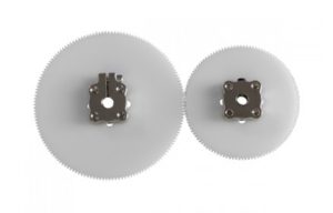
Hub gears, with mounting hubs (left clamping, right set-screw) attached.
Pinion gear attached to a ‘D’ shaft.
-
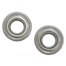
Flanged bearings.
Bearings, Hubs, Collars and Other Minutiae. You will need a bunch of bearings (mine are 1/2″ OD, 1/4″ ID), and some bearing to spacers to go with them. Flanged bearings are generally the most useful. The main gear needs a mounting hub to connect it to the drive shaft, and that hub has to be the clamping type (set screw type will distort the brass tube). Collars are needed to stabilize both the idler and main drive shafts. Don’t forget screws and a ball-end hex key.
-

Stepper motor.
The Stepper Motor and its Mount. Stepper motors are tricky to select because they are all over the map in terms of voltage, amperage, steps per revolution, size (form factor), etc. I chose a 200 step motor from Sparkfun that runs at 12 volts, but a relatively low amperage (.33A), and for which a mount is available. The motor’s shaft is 5mm, so a 5mm to 1/4″ shaft coupler is needed. Additional parts needed to mount the motor included standoffs, a single channel flat bracket and a couple of attachment brackets. Finally, I needed a bearing block to support the shaft attached to the stepper output.
-
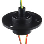
A Slip Ring. The shaft on the top rotates.
The Slip Ring. When you look at the strategies in past decades for supplying power to a turntable bridge, you typically see some kind of wiper system for supplying power to moving feeders. Thankfully it is no longer necessary to build such contraptions; instead what you need is a slip ring. Slip rings have incoming leads on the stationary side, and outgoing leads on a rotating shaft on the moving side. Internally they have a high durability wiper system for transferring power from the stationary to the moving sides. The only downside of the Sparkfun slip ring collection is that it is not configured for the Actobotics system; the mount for the stationary part does not match an Actobotics mounting pattern. So, as you’ll see, I had to compromise a little to make it work. I bought the 6 wire/ 2 Amp version.
- Position Sensors. Stepper motors are very precise. Theoretically, once a stepper driven mechanism is set up and calibrated, positioning should be accurate indefinitely. But the mechanism could get knocked out of alignment; and there should be some tools to aid calibration initially and to make sure the bridge is in its calibrated position at the start of a session. So I needed a position sensor of some sort. What I decided to do was place a pair of magnetic reed switches at a spot on the pit (behind the wall, out of sight). One end of the bridge has a hidden magnet that will trip the switches. When the magnet is between and tripping both switches, the bridge will be in position 0, and all other positions can be calibrated from there. It should work …. but we will see.


Step 4: Assemble and install the turntable.
It took several months, and a lot of trial and error, to come up with a working turntable mechanism. So, getting back to the project in hand, it is time to assemble and install the turntable into the layout.
But first, a little detailing ….

The pit after some painting and detailing.
It occurred to me that once installed the pit would be difficult to detail. So, having disassembled the mechanism to prepare it for installation, I painted the interior of the pit, detailing the circular support/drive rail with cinders and spreading a little earth blend ground foam on the pit floor. After placing a few weeds, I declared it ready to install.

Underside of the pit, showing the magnetic reed sensors (bottom), stand-offs epoxy’d to the pit for attaching it to the Actobotics system, and a solid shaft I used for alignment during assembly.
Here is “the big picture” of how all the parts go together:

The completed turntable mechanism, with mounting blocks attached.
The mounting method may seem complex, but it is necessary to minimize the space occupied by the mechanism. My early attempts, which required putting the main gear beneath the channel, were too tall for the available space. Putting the gears between the pit and the channel turned out to be the most space efficient arrangement; the only one that allowed enough space for the spinner. With this assembly installed, there remains 1/2″ clearance between the spinner and the table top the layout is resting on. Excellent.

Turntable drive detail.
You’ll notice that the output side of the spinner is slightly off-center relative to the main drive shaft. The output shaft of the spinner it too large to fit inside the brass tube, so it has to be mounted independently. As I mentioned above, the mounting holes on the spinner do not match the Actobotics mounting system. However, I found that I could anchor the spinner using two of the three mounting holes; the trade-off is that it is not perfectly centered.
Is this a problem? Probably not. The turntable moves slowly, so the wires should not be unduly flexed by the off-center mount; the output side spins freely, so little stress will be exerted on the wires. As always, of course, we will see under actual use conditions.

The turntable from below after installation.
The installed turntable, ready for the next stage of build-up.
What’s Next?
Next step is to lay the remaining track for the roundhouse/turntable area, build up the rim of the pit, then build the deck and central arch of the bridge and finish bridge wiring. From there its on to the electronic controls and the initial calibration of the system. Along the way I’ll also be doing the basic scenicking (a little sculptamold, paint and ground foam) of this zone while I have easy access without taking the layout apart.
Until then, happy railroading!
Good day Robin!
Have you gotten around to a way to control the turntable?
I was going to use the stepper motor also.
I have seen several way to control it with the Arduino, but none of the sketches will do what I need.
They all seem to use the motor driver board from Adafruit.
I have 2 turntables to control with DCC that are fairly simple, only 4 – 6 rays.
They are Peco NB55 turntables.
Thank you!
Hello Jay,
I do have a control system based on the Spark Fun Easy Driver board (microstep mode gives really smooth, scale speed motion).
Right now I’m in the process of working out the indexing. I will be doing a new post soon on the whole system – I hope before the end of the month.
Best,
Robin
I did forget to add, both of my layouts are DCC. Also, both are running Digitrax.
Good evening Robin!
Have you made any headway on this project?
Thanks!!
Jay
Hi Jay,
I’m close to getting a blog post out — I haven’t finished the indexing and testing yet and I’m splitting my time with some more conventional modeling on the next module. Should be able to get something out in a few weeks. Robin
Hi Robin!
Just checking in once again.
No big hurry, I have many projects in work right now.
I was just wondering when the blog post will be done.
Thank you!!
Jay
Hi Jay — Appreciate your interest. I’m getting caught up again and, with some downtime coming this week, should get the next post out by next week. Best, Robin
Hi Robin,
Nice project. Although I switched from N to H0 while my eyes needed a lot of help I am still interested in what is going on in the N-world. I was looking for a DIY mechanism for turntables operated with arduino and stepper motors when your page was found. Really nice work.
Thank you! A follow up post is coming soon.
Hi Robin! Did you write a post already?
Just checking again.
Jay
Yes. Its at the top of the blog.
http://thenscaler.com/?p=1366