After a long pause, I’ve starting in on wiring the L&NC by doing the basic wiring on module 1, lower level (each module has two levels). Module one is the largest of the three modules at 54″ long, and is the intended entry point for all the incoming power and control connections. Everything I do here is intended to set the methods and practices for the remaining modules.
Applying Lessons from the Past
My early layouts were primitive from a wiring perspective (and other perspectives…. but lets not dwell on that ….). I never did get into the suitcase connector thing, but the old layouts were wired using a single bus pair connecting to feeders every few feet. Not much to it, so there was not much to organize. Like many layouts, the wiring was somewhat exposed and disorganized underneath.
While I was experimenting on the Test Loop, the wiring was built up in layers without a master plan. For example, the power distribution from a central barrier strip was fine at first, but later it became necessary to create secondary distribution points to support various power needs. I ended up with wiring less than optimally organized. On the plus side, I found that small circuit boards with banks of screw terminals are an excellent way to distribute power to to individual feeders or devices.
The other major lesson from the test loop is that it is a pain in the rail to add a major electronic component after everything else has been wired up. Major components should be sited and accounted for before interconnecting anything. Components that move—e.g., servos, turntable mechanisms or whatever—get priority to ensure they get the placement and space they need — everything else has to adapt to their needs. In this case I will be installing the servos and the turntable early … but I’m getting ahead of myself again.
Special Issues with the L&NC
The L&NC has to be wired with a different aesthetic given that it is intended to be dissembled, moved and reassembled reliably. I am using the Digitrax Empire Builder DCC system, along with my Arduino-based independent control system and a multi-voltage power system supporting the layout — with power provided by a converted computer power supply. Computer power supplies can furnish 300 or more watts of fully regulated power at 12, 5 and 3.3 volts, perfect for every need other than track power.
The lower level of module 1 (left-most module in the drawing) is fairly complex to wire because it contains the Red Bluffs Yard and the Roundhouse/Turntable complex. Including the feeders needed for the Roundhouse/Turntable area, 24 track feeders with current sensors have to be managed.
Yikes! That’s a lot of feeders for a 54″ x 27″ layout section! Its because of the yard, Roundhouse and turntable. Each roundhouse bay, the turntable bridge and any adjacent track segments adjoining the turntable all need individual feeders; the turntable is a reversing segment. Then each leg of the yard needs feeders, plus the base feeder for the ladder, to support occupancy detection and reliable operation. The main track loops each have two feeders. It all adds up…
So there is a lot more wiring in the L&NC than might be considered normal, and it has to be secure and well organized.
Step 1
With most track laid (I’m deferring the Roundhouse area until the turntable is installed) and the locations of all feeders and turnouts established, the first step is to place the primary distribution nodes then route, terminate and secure the main power bundle, the track bus and the LOCONET bus.
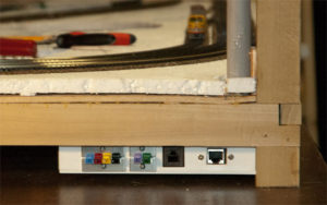
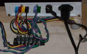
At the far left end of the module I placed a connection panel fabricated from styrene. There are four connections:
- Main power (4 conductors: 12 volt, 5 volt & 3.3 volt, plus ground);
- track power connection (2 conductors: Track A & Track B);
- LOCONET RJ12 jack (6 conductors); and
- Ethernet RJ45 jack (8 conductors).
My primary color coding scheme:
- Black = Ground
- Yellow = 12 volts DC
- Red = 5 volts DC
- Blue = 3.3 volts DC
- Green = Track A (right-hand rail)
- Violet = Track B (left-hand rail)
For the two power connections, I’m using Anderson Powerpole 15 Amp connectors to create polarized, color coded connectors. 2 connector and 4 connector brackets secure the receiving connection to the panel. I really love these connectors because they are easy to assemble (provided you invest in the crimper), come in a wide variety of colors, allowing you to assemble plugs and matching receptacles that can only be connected together one way. I get my supplies from Powerwerx.com.
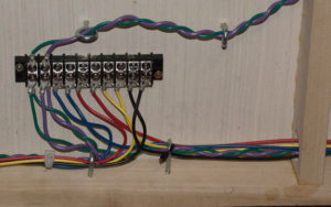
From the panel, the wires run a few inches to a barrier strip. Here the power is split – one branch going off to feed other parts of this level, with another branch heading to the upper level.
To supply power to the upper level I installed a short piece of PVC pipe from underneath the module, running up next to the corner post, terminating above the bottom edge of the upper level (when installed) I ran wires from the barrier strip up through the pipe, leaving 8″ or so extra cable extending from the top of the pipe, terminated with Powerpole plugs coded for the two power bundles.
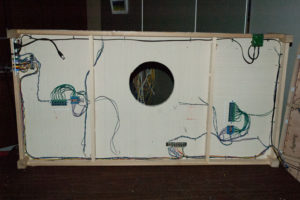
To get to other areas of the lower level I ran cables from the first barrier, along the edge of the frame, using screw-in eyelets every 6 – 8 inches to channel the cables. I terminated the cable run at a strip near the middle of the module, then ran an addition set of cables from the middle strip to the right hand edge of the module. Leaving 8 inches of slack, I terminated the cables with Powerpole plugs to be connected to a panel on the adjoining module.
The RJ11 jack has leads that I soldered to a six wire cable, then run that cable along the front edge of the module, opposite the power cables, to the location of a Digitrax UP5 universal panel (attached to the frame pending the addition of fascia), terminating the cable with an RJ11 plug as required to attach to theUP5. I fabricated another cable to run from the UP5 to interconnect bundle at the right side of the module.
The Ethernet jack on the panel is one end of a prefabricated cable available from Adafruit Industries. The other end will connect to a small Ethernet switch which will install at a later date. From there I’ll make custom Ethernet cables (my crimper does both 6 and 8 conductor connectors) to fit where needed. Ethernet wiring will be added after I know the location of the Arduinos it will be supporting. I have an 8 port unit ready for the task.
I set up two track power distribution areas with a current sensor for each block, one on each end of the module. At this point I’m keeping the center area clear pending installation of the turntable. A third distribution area will be setup in that area to service the Roundhouse, turntable, service and approach tracks.
Now that the basic wiring is in, its time — finally! — to test the track installation, and fix what ever problems I find before moving on to the next step. Until then, happy railroading!


One thought on “Wiring Module 1 of L&NC”