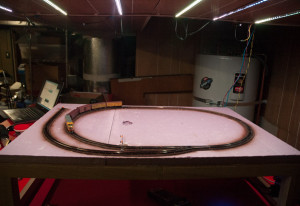
I built the test loop for a couple of reasons. First I needed to revive my long unused track laying skills. Second, I needed a place to test and repair locos and rolling stock. Third, and perhaps most importantly, I needed to learn how to deploy Arduinos on a layout in a bullet-proof sort of way, before investing time and money building the main layout.
If you’ve been following along, you know that lighting is one of my big challenges in building the layout in the chosen location. The soffits above the bar are a thin skin of paneling, with little structure supporting it, hiding HVAC duct-work. Standard light fixtures are not possible here.
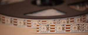
That constraint started a search for a lighting solution that was light enough to affix to the paneling with 3M Command Strips, but would produce enough light to effectively light the layout. When I found strip ALEDS, I knew I’d found a solution. The first two light bars I made are demonstrated here (a simple light show accompanied by a little Debussy):
The bars are easy to create. Mine are sized at 26″ long; the right size to both light from above and install on the underside of the top level of the layout to light the lower level.
To make them I split 1/2″ PVC pipe on a table saw, then cut the pipe halves to length [TIP: PVC pipe from your home store is dirty stuff. I clean the cut halves with denatured alcohol before final assembly]. I attach 1/2″ reflective Mylar tape to each inside half of the pipe (creating a reflector), leaving a strip of bare PVC down the center of the pipe. A bead of Liquid Nails for Projects down the middle holds a prepared (with JST 3 wire connectors at each end) 38 LED strip.
The demo above shows two bars chained together. You can keep lengthening the array by adding additional bars, at least until you reach the limits of your power supply.
Not So Fast
I have to admit that when I made and tested 4 bars together (152 LEDS), I was disappointed with the amount of light I was getting. It was good, but just not quite enough. Two more bars (228 LEDS) ought to do it I thought.
What I got when I expanded the array to 6 bars was a very obvious light intensity drop off (and resulting color change, since these are RGB LEDS) from the beginning to end of the array. Nowhere in the information I’ve assembled about ALEDS has there been any mention of this problem. I got out the multi-meter and, sure enough, the supply voltage drops steadily as you progress along the strip; and the greater the total number of ALEDS chained together, the more pronounced the effect throughout the strip.
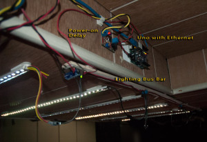
Well, I’m a model railroader and I know all about resistance and current drop off; this is our classic problem of current loss over long runs. The solution? A 16Ga supply bus that injects current every two bars.
A strip of plywood provides the mounting surface for the required capacitor near the first LED, the bus wire (I CA’ d it to the wood) and circuit board fragments with with PCB screw terminals.
Problem solved.
Booting a Loaded Arduino
The basic reliability of the Atmel platform used by Arduino boards is impressive. So when I started seeing boot problems, I was puzzled. In all cases, the problem occurred on initial power up; rebooting the affected board by hitting the reset button solved the problem.
This was not a good development.
My first three loaded up Arduinos are installed on the Test loop, Lighting Control and the Control Panel. All three have an Ethernet Shield and are attached to additional devices. All three evidenced cold boot problems in one form or another.
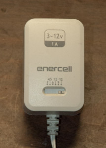
It had to be a power problem. The additional load from the Ethernet Shield and other devices (although, in most cases I supply power to attached devices separately so they don’t draw from the Arduino’s limited current handling capacity) had to be the issue. One of the confusing things about UNOs is that you can power them from USB at 5 volts DC, or from a separate DC power supply at 7 – 12 volts.
Umm, how much power should I be supplying?
In the context of the control panel, where an UNO has an Ethernet shield with multiple digital and analog connections to the touchscreen, I found that I need to supply 12 volts. At that level the rig is 100% reliable, something I easily established with the help of an adjustable power supply. The trade-off with the control panel, because everything is enclosed, is heat buildup, requiring a fan I didn’t originally plan for.
New deployment rule: the standard power supply for Arduino boards with built-in voltage regulators (primarily UNOs and MEGAs on this project) will be 12 volts DC. Connected devices will run at the standard logic 5 volt level. Smaller Arduino boards without a voltage regulator will get 5 or 3.3 volts DC as required.
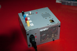
I use converted computer power supplies with simultaneous outputs at 3.3, 5 and 12 volts DC, so my layout bus has all three feeds.
It may not seem like it, but that is progress.
Powering Up In Order
Unlike the control panel, the lighting controller did not settle down with a 12 volt supply. There, the Ethernet Shield would go into an initialization loop (attempting to start up and failing, over and over) on power up — but would work fine after a hard reset.
On the test loop, the problem was even subtler: upon cold power up everything appeared normal and the sketch would start to execute…. then freeze at the point where it is supposed to send a broadcast message across the network.
It had to be something about power again that manifests only on a cold start, but what? Faulty Ethernet shields?
Here the clue was a little warning from Adafruit about neopixels (ALED strips): always make sure the power supply to the strip is on before the data connection from the Arduino goes live, or the strip could be damaged.
I always figured that if the Arduino and the ALEDS (and other peripheral sensors and actuators) were powered from the same source and came on simultaneously, Adafruit’s warning would be satisfied. Since I’ve never had damage to the strip, and I’ve been working with the same strip for some months now, I think technically I was right. However, it seems that from the Arduino side, simultaneous start up is not necessarily so blessed, especially when attached to an Ethernet shield.
I conducted a simple experiment on the lighting controller: I unplugged the power from the board/shield combo then powered up the ALEDS before plugging the power into the board.
BAM. Worked perfectly every single time. No confused Ethernet shield; perfect response to commands; no hitting the reset button.
Of course, manually plugging a fleet of embedded Arduino boards was not going to do at all.
Automating Power On Delay
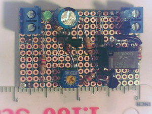
Consulting the Internet Machine, I found a simple power-on delay circuit. In my first attempt I built it as shown, except for substituting a variable resistor for R2 (on original schematic) to allow some adjustment of the delay. For the relay, I chose a low power signal type — adequate for the power draw of the Arduino/Shield, but possibly not sufficiently durable for this application. Only long term experience will tell.
Anyway, as built it provides about a 50 – 100 millisecond delay in powering on the board. That turns out to be enough. With the delay circuit attached, the lighting controller powers up perfectly every time.
I modified the circuit slightly for my second build, including both input and output indication LED’s [ green for input power on, and blue for output power on. ] and increased the size of the capacitor to 100µf. The bigger capacitor gives a little more time range to the delay (as adjusted by R4; if you go out of range either direction on R4, the circuit will not work.) from about 1/10th to 1/2 second. The I/O LEDs really help see the timing of the delay.
Here’s schematic of the board as I’m building it now:
Built on one quadrant from an SB4 Snappable Breadboard (these are my go-to, two sided solderable breadboards), the top looks like this:
And, the bottom:
Installed on the test loop and in operation:
From here on, power on delays circuits are another standard component for reliable operation, though I think I’m going to double the size of the resistor on the blue led to tamp down its brightness more!.
