
Programming an Arduino to run turnouts, lights or animation on the layout is only part of the challenge. The other part is how do you control the board and tell it what you want it to do?
From an Arduino point of view, any sensor attached to a pin can trigger action in a sketch. As shown in Turnout Control with Arduino & Servos, mechanical buttons and switches can be attached to pins to tell the board what to do. In the example circuit, a single button triggers servo action. If you want to include feedback indicators as in this example circuit — these could be layout signals or panel indicators — you can hard-wire everything together to the same Arduino board.
Until you run out of pins
Pin management is critical as you ask the Arduino to do more and more. Every new sensor or triggering device consumes pins (as does every new actuator or output device). While learning what I could do with an Arduino on the layout, I realized that I needed get beyond the hardwired controls used in experiments and demos to a generic, software-based control system. To do that I was going to have to network everything together.
Networking Arduinos
In Roundhouse Rebuild Part 2 I mentioned, without explanation, that I was using Ethernet, and went on to discuss the evolving Simple Network Command System. I decided to go with wired Ethernet because of the easy availability of inexpensive Ethernet shields based on the WIZnet W5100 Ethernet Controller chip (under 10 dollars per shield), and an easy to use Arduino library included in the IDE. It is as close to plug & play as networking gets on an Arduino. The only additional equipment required are one or more inexpensive 10/100 switches (for example: TP-LINK TL-SF1005D 5-port 10/100Mbps Desktop Switch; don’t get gigabit switches to work with these shields, you’re just asking for trouble) to interconnect the devices. I use a per-device assigned address system which helps keep the equipment roster simple (no router or DHCP required).
Why not just use the Digital Command Control system for the Arduino net? The short answer is that while it is clearly doable, for the purposes of this project I am going to keep the Arduino net separate because:
- Everything I do here has to work for both DC and DCC layouts. I own both DCC and unconverted DC locomotives; the layout has to work the same in either mode.
- Compared to conventional networking, DCC is a relatively difficult way to conduct bidirectional communications between Arduino boards.
- Keeping them separate does not preclude enabling communication between the two systems down the road.
If you want to pursue DCC communication and Arduino, the Model Railroading with Arduino site is a great place to start. The biggest impediment for most modelers will be the lack of commercial interface hardware to connect an Arduino to either track power or the command bus (although the circuits are easy enough to build); the closest commercial solution would be to use a USB interface, like the Digitrax PR3XTRA USB Programmer, RR-CirKits LocoBuffer-USB or the SPROG II USB, to tap into the DCC command system just as you would with JMRI.
My ultimate goal is to build the layout’s electronic and mechanical foundation around a network of Arduino boards. For communication among Arduino boards, Ethernet makes the most sense right now because it is the most “frictionless” route to achieve my goals (a wireless form would be even better, but would be a little more difficult to implement, so I’m holding that option for the future); communication between the Arduino net and the DCC system is a topic for the future—and the possibilities go way beyond treating Arduinos as decoders.
Building The Controller
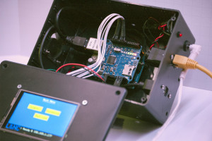
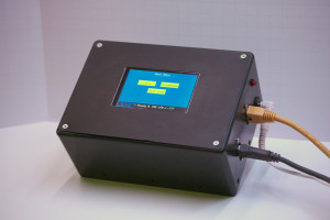
The concept for a prototype controller was simple enough: start with an Uno, add an Ethernet shield and add a small touchscreen for display and user input. Put it all in a box with an Ethernet jack, a USB jack and power connector. Software generates screen displays, interprets touches and communicates with devices it is controlling.
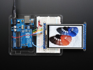
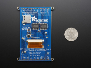
For the screen I chose the Adafruit 3.5″ TFT Touchscreen, seen here attached to an Uno via a breadboard (NB: The wiring shown is the minimum required to run the screen; the touch overlay and the SD Card reader require additional connections). It is capable of full 16bit color with a resolution of 320 x 480 pixels. The Adafruit library provides basic graphic primitive functions, basic text functions and bitmap functions allowing image display. It has a resistive touch overlay. Adafruit has an excellent tutorial on using this screen with their library.
The screen comes with a choice of interfaces: you can use the SPI bus interface in order to use the fewest pins on your Arduino, or you can devote more pins to use the faster 8 bit interface. You select the interface and solder the header pins on the appropriate side. A solder jumper on the back determines which interface is active; the decision is reversible. An SD Card reader is included for convenient storage of bitmap files.
On an Uno, the Ethernet shield dictates that the TFT screen has to be run via SPI; there aren’t enough pins otherwise. The application does not require the SD Card Reader so I don’t connect it to the UNO.
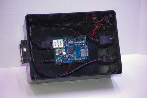
I fabricated a wiring harness for attaching the screen to the Uno\Ethernet combo, then mounted everything in a Radio Shack project box as shown below.
The connectors on the wiring harness are male or female PCB Headers; I solder the wires to the PCB side of the fittings, then cover each connection with heat shrink tubing. White wires connect to digital pins 7 through 13 (except 10, which is reserved for the Ethernet shield) and are for the TFT interface. Green wires are for the touch overlay and connect to Analog pins A2 – A5. Red supplies 5v, and black ground, to the TFT screen. The Ethernet extension cable and the USB extension cable both came from Adafruit.
Here it is in operation:
You may have guessed the fan ( on the left side ) was an afterthought. The cheap Ethernet shields I use are heat sensitive; they will crash when put in a confined space with poor air circulation. Out in the open no problem; in a box, its a problem. Found that out the hard way. So I added a little fan to pull the air through the box (if you look closely, you’ll see there are holes around the bottom); works fine if noisily. Obviously, I will plan for air circulation when I build the main layout control panel. Such is prototyping!
What it Does
The controller sketch displays menus with buttons that, when touched, will cause the controller to either go to a different menu or send a command packet to the target device. Command packets are strings, formatted thus: function / option / data. For more about my protocol and the network polling process, see the Simple Network Command System section near the end of Roundhouse Rebuild Part 2.
The Main Menu provides access to sub-menus that I’ve created to support parts of the project.
All menus are built with buttons. A structure type called button_t holds button data:
typedef struct {
  int x;
  int y;
  int txtX;
  int txt;
} button_t;
X and y are the coordinates of the upper left corner of the button; the width and height are the same for all buttons in this version of the system. txtX is the x coordinate for the button text; the y coordinate is calculated and there is no text centering function. Finally, txt is an offset into a button_labels array pointing to the button text.
For the main menu, the button set definition looks like this:
const button_t buttons_main[SIZE_MAIN_SET] = {
  {90, 80, 115, 0 },
  {250, 80, 254, 1},
  {175, 140, 185, 16}};
Determining if a button has been touched is fairly straight forward. The coordinates of a touch p are compared to each button, as b, in the current set to see if it is on or within the button boundaries.
p.x >= b.x && p.x <= (b.x + BUTTON_WIDTH) && p.y >= b.y && p.y <= (b.y + BUTTON_HEIGHT)
Whacking My Head on the Memory Ceiling
The graphics libraries contain a lot of code. With the newest Arduino IDE, the controller sketch compiles to 27,030 bytes, about 83% of available program space; it was about 29k bytes with the previous IDE.
That is still tight enough that I cannot include SD Card access and a function to draw a bitmap from a file without going 15% over the absolute memory limit for an UNO. In the future I’ll use an Arduino MEGA 2560 Board instead of an UNO for control panel applications because of its vastly superior memory resources (and it has a lot more pins to work with). The remaining 17% with the current sketch gives me plenty of room for now.
The trickier bit of memory management is “dynamic memory,” which (on an UNO) is 2,048 bytes of shared memory space used for local variables. Local variables are created when functions are called and destroyed when they are exited. Global variables–variables declared outside of any function that are always in scope and available wherever you are in your sketch–are also stored in the same space. Global variables reduce the amount of dynamic memory available for local variables and, if not managed, can strangle your sketch.
Fortunately, the majority of global variables turn out to be constants — unchanging values or text used by the application. This kind of data can be stored in the program space instead of dynamic memory; the limitations are that
- you can’t change the value stored in program space while the sketch is running, and
- you have to copy a value from program space to dynamic memory in order to use it.
The PROGMEM keyword is used to tell the compiler to store something in program space instead of dynamic memory. To park menu titles and button text in program space, I did this:
const char mstr_0[] PROGMEM = "Main Menu";
const char mstr_1[] PROGMEM = "Lighting Menu";
const char mstr_2[] PROGMEM = "Roundhouse Menu";
const char mstr_3[] PROGMEM = "Test Loop Menu";

const char* const menus[] PROGMEM = {mstr_0, mstr_1, mstr_2, mstr_3};

const char str_0[] PROGMEM = "Lights";
const char str_1[] PROGMEM = "Roundhouse";
const char str_2[] PROGMEM = "<-Back";
const char str_3[] PROGMEM = "  Night";
const char str_4[] PROGMEM = "   Day";
const char str_5[] PROGMEM = " Mid-Day";
const char str_6[] PROGMEM = " Sunrise";
const char str_7[] PROGMEM = " Sunset";
const char str_8[] PROGMEM = "   Low";
const char str_9[] PROGMEM = "  High";
const char str_10[] PROGMEM = " Stall 1";
const char str_11[] PROGMEM = " Stall 2";
const char str_12[] PROGMEM = " Stall 3";
const char str_13[] PROGMEM = " Stall 4";
const char str_14[] PROGMEM = " Stall 5";
const char str_15[] PROGMEM = "Afternoon";
const char str_16[] PROGMEM = "Test Loop";
const char str_17[] PROGMEM = "Main";
const char str_18[] PROGMEM = "Siding";
const char str_19[] PROGMEM = "Occupancy";

const char* const button_labels[] PROGMEM = {str_0, str_1, str_2, str_3,
 str_4, str_5, str_6, str_7, str_8, str_9, str_10, str_11, str_12,
 str_13, str_14, str_15, str_16, str_17, str_18, str_19};
Copying the title of the main menu into a local variable text looks like this:
strcpy_P(text, (char*)pgm_read_word((&menus[0])));
For getting the button labels:
strcpy_P(text, (char*)pgm_read_word((&button_labels[b.txt])));
An alternate way to store static data in program memory is to use the F macro, as in this declaration of a local variable that initializes with a static value that is stored in and retrieved from program memory:
String readyStr = F("Ready");
At this point I find it useful to make it a habit to use these tools in all sketches to tame dynamic memory space. Currently the controller sketch uses only 771 bytes or 37% of dynamic memory for global variables, leaving plenty of space for locals.
Menus
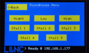
The Lighting and Roundhouse menus look like this:
These are the controls I used off screen to control lighting when making the Roundhouse demo video. Overhead lighting was supplied by 4 led light bars (152 RGB ALEDS total) controlled by a networked UNO.
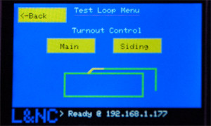
I’ve been busy at the test loop trying out various ideas. Turnout control, signals and block occupancy detection (I have a method that works for both DC and DCC layouts), all play a part in the next step toward the layout. I’ll leave you to ponder the test loop menu until next time.





Hi, Nice to meet you. My name is Justin Kim, at WIZnet in Korea.
We have been searching some application references in which WIZnet solution is applied, and found your project “programmable layout controller“ using Ethernet Shield. In the Ethernet Shield WZnet’s W5100 chip is embedded.
Your development looks very cool & smart. Recently we opened WIZnet Museum (http://wiznetmuseum.com) site. This is a academic-purposed collection of open projects, tutorials, articles and etc from our global customers.
If you are O.K. we would like to introduce your projects in here. Hopefully, you will allow this. Also, if you are interested, we would like to introduce the Ethernet shield of our latest chip version, W5500 or WiFi Shield. You may be able to establish another project with them. Hopefully, keep contacting us for the friendship.
Thank you very much
Hi Justin, thanks for visiting. I would be honored to have my work included at wiznetmuseum.com. I’ll be in touch.